background image

A

OPERATING INSTRUCTIONS

17

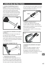
2. Auxiliary handle fitting (see fig 4)
NOTE: 

The handle may already be pre-

fitted to the trimmer. However the following 
instructions give full assembly details.
Attach the auxiliary handle to the bracket, 
note orientation. Insert the auxiliary handle 
adjusting bolt through the handle and the 
bracket and tighten the bolt clockwise.

Fig 5

3. Assembling the extandable arm support 
(see fig 5)

The extendable arm support will make your 
trimming job more comfortable.
Press the two buttons on the support shaft and 
insert into the shaft into the top of the trimmer. 
The support can now be extended or retracted 
to the desired position.

PREPARING TRIMMER FOR USE

Fig 6

1. Adjusting Auxiliary Handle

The auxiliary handle can be adjusted to suit 
the operator. To move the handle, release the 
tension on the handle retaining bolt by turning 
the knob counter-clockwise. Adjust the handle 

to the desired position and retighten the bolt by 
turning it clockwise. The handle is now locked 
in the desired position (see fig. 6).

Fig 7

unlock

lock

2. Adjust the height (see fig 7)

Turn the height adjustment locking knob 
counter-clockwise to unlock. The telescopic 
tube can now be moved up or down to achieve 
a comfortable working height.
To lock the tube in position, turn the locking 
knob clockwise.

Fig 8

3. Adjusting the extendable arm support 
(see fig 8)

Pull the arm support outwards in order to 
extend it to the desired length - so that 
the support is underneath the elbow. The 
extendable arm support is designed to provide 
extra support for one hand trimming.

Summary of Contents for GGT600LU

Page 1: ...Manuel d utilisation Operating Manual COUPE BORDURE15PO 38cm DE5A 325600 GGT600LU 15 38cm 5AMPTRIMMER 325600 GGT600LU A F 2 12 13 24 ...

Page 2: ...luie c Maintenir éloignés les enfants Tous les visiteurs doivent rester éloignés de la zone de travail d Utilisez des vêtements adéquats Ne portez pas de vêtements amples ni de bijoux Ils peuvent s accrocher dans des pièces mobiles Il est conseillé d utiliser des gants en caoutchouc et des chaussures robustes lorsque vous travaillez à l extérieur Attachez les cheveux longs e Utilisez des lunettes ...

Page 3: ...nez une bonne position et l équilibre à tout moment o Restez concentré Regardez ce que vous êtes en train de faire Utilisez votre bon sens N utilisez pas le coupe bordure lorsque vous êtes fatigué p Débranchez l appareil Débranchez l appareil de la source d alimentation lorsque vous ne l utilisez pas avant de le réparer lorsque vous changez des accessoires tels que les lames ou autres q Conservez ...

Page 4: ...ANTS V Volts A ampères Hz hertz no vitesse à vide courant alternatif Isolation double min Rotation par minute SYMBOLES DONNÉES TECHNIQUES Tension 120 V 60 Hz Ampérage nominal 5A Vitesse à vide 7500 t min Diamètre coupe max 15 po Grosseur de fil 065 po Poids 7 7 lbs 3 2 kg Double isolation Lisez le manuel Avertissement Ne pas exposer à la pluie ou à l eau Ne pas jeter au feu Portez des lunettes de ...

Page 5: ...bine 17 Taquet du couvercle du compartiment à bobine aux deux côtés 18 Bobine 19 Fil de coupe 20 Couteau pour fil de coupe ACCESSOIRES INCLUS Appui bras Protecteur Poignée auxiliaire Roue guide pour bordures ASSEMBLAGE PRUDENCE Avant d utiliser votre coupe bordure assurez vous d avoir lu le manuel d instructions avec attention Le protecteur doit toujours être en place sur l outil pour protéger l u...

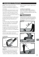
Page 6: ...peut maintenant être ajusté en longueur à la position désirée PRÉPARATION DU COUPE BORDURE POUR SON UTILISATION Figure 6 1 RÉGLAGE DE LA POIGNÉE AUXILIAIRE La poignée auxiliaire peut être réglée selon les besoins de l utilisateur Pour déplacer la poignée relâchez le boulon de retenue de la poignée en le tournant dans le sens anti horaire Réglez la poignée à position désirée et resserrez le boulon ...

Page 7: ... la poignée en poussant le manche vers le haut ou vers le bas Figure 10 Figure 11 5 Réglage de la poignée principale voir Figure 10 et 11 La poignée principale à 2 positions Elle peut être ajustée pour usage à une main ou à deux mains Pour ajuster la poignée tournez le bouton de déclenchement dans le sens anti horaire placez la poignée et reserrez le bouton en tournant dans le sens horaire 6 Régla...

Page 8: ...Figure 15 Figure 16 Figure 17 Figure 18 7 Remplacement de la bobine et du fil voir Figure 12 à 18 Toujours débrancher le cordon d alimentaion de la source électrique avant de changer la bobine du coupe bordure Renversez le coupe bordure afin d avoir accès à la bobine Tenez d une main la tête du coupe bordure et de l autre pressez sur les boutons de relâchement qui sont situés de chaque côté de la ...

Page 9: ... passer le fil de coupe au travers des deux oeuillets dans le couvercle de la tête Tirez fermement sur le fil afin qu ils soit dégagé des crampons Replacer le couvercle de la bobine par dessus la tête de coupe Assurez vous que les boutons de relachement soient bien en place UTILISATION Figure 19 1 Mettre le coupe bordure en marche voir Figure 19 Branchez le coupe bordure dans une prise AC Pressez ...

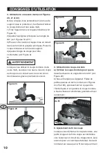
Page 10: ...urez vous que la roue de coupe est toujours en contact avec le sol car sinon des blessures graves pourraient survenir Figure 23 Figure 24 Figure 25 Figure 26 4 Utilisation du coupe bordure a Inclinez le coupe bordure pour que le travail se fasse à un angle d environ 20 voir Figure 23 b Ne surchargez pas l appareil Faites de petites passes en demi cercles voir Figures 24 25 et 26 spécialement en co...

Page 11: ...rdure pour des travaux de taille bordure appuyez sur le bouton situé dans la poignée et tournez la poignée dans le sens anti horaire de 180 voir la figure 26 Le rouleau situé sur la tête de coupe aidera à guider le taille bordure le long de la bordure ENTRETENEZ VOS OUTILS AVEC SOIN Votre outil ne nécessite aucune lubrification ou entretien supplémentaire Il ne comporte aucune pièce à réparer ou à...

Page 12: ...hniciens en service et ce de 9 h à 21 h du lundi au vendredi heure normale de l Est La garantie ne porte pas sur l usure normale y compris l usure des accessoires Le produit est garanti pendant 36 mois s il est utilisé à des fins normales Toute garantie devient invalide si le produit a été surchargé ou soumis à un usage négligent ou inadéquat ou si une personne autre qu un agent autorisé a tenté d...

Page 13: ...stance from the work area d Dress properly Don t wear loose clothing or jewelry They can be caught in moving parts Use of rubber gloves and substantial footwear is recommended when working outdoors Wear protective hair covering to contain long hair e Use safety glasses Always use face or dust mask if operation is dusty f Use right appliance Do not use appliance for any job except that for which it...

Page 14: ...ance indoors When not in use trimmer should be stored indoors in a dry and high or locked up place out of reach of children r Maintain appliance with care Keep cutting edge sharp and clean for best performance and to reduce the risk of injury Follow instructions for lubricating and changing accessories Inspect appliance cord periodically and if damaged have it repaired by an authorized service fac...

Page 15: ...Line Diameter 065 Weight 7 7 lbs 3 2 kg Double insulation Read the manual Warning Do not expose to rain or water Do not burn Wear safety goggles dust mask and eye protection Double insulated To avoid possibility of electric shock do not use in damp or wet conditions Switch off Remove plug from power supply before adjusting cleaning or if cable is tangled or damaged Keep all other people including ...

Page 16: ...Spool head cover latch on both sides 18 Spool 19 Trimmer Line 20 Trimmer Line Cutter INCLUDED ACCESSORIES Arm Support Guard Auxiliary Handle Guide Wheel for borders ASSEMBLY WARNING Before using your grass trimmer be sure to read the instruction manual carefully The guard must always be on the tool to protect the user Fig2 Fig 3 1 Guard fitting see fig 2 3 Attach the guard to the motor housing not...

Page 17: ...E Fig 6 1 Adjusting Auxiliary Handle The auxiliary handle can be adjusted to suit the operator To move the handle release the tension on the handle retaining bolt by turning the knob counter clockwise Adjust the handle to the desired position and retighten the bolt by turning it clockwise The handle is now locked in the desired position see fig 6 Fig 7 unlock lock 2 Adjust the height see fig 7 Tur...

Page 18: ...e turn the release knob counter clockwise adjust the handle and retighten the release knob by turning it clockwise 6 Adjusting the cutting line The machine is equipped with an automatic line feed system there is no need to adjust the trimmer line by hand When initially switching on the trimmer a small length of line is fed out A clattering noise will be heard for a short time This is normal and is...

Page 19: ...ine in the spool is 10 ft 3 m per line Take approximately 10 ft 3 m of line and insert 5 8 15 mm of line into the hole in the upper section of the spool Wind the line in the direction of the arrow on the top of the spool Leave approximately 4 100 mm of line unwound and place it into the cleat Repeat on the lower section of spool Care should be taken to ensure that the line is neatly coiled on the ...

Page 20: ...to a complete stop Fig 20 Fig 21 Fig 22 3 One hand operation see fig 20 21 and 22 The extendable arm support and the under guard roller support make it convenient to operate the trimmer with just one hand 1 Pull the arm support to the desired length see fig 8 2 Adjust the main handle to the 90 right angle position see fig 10 and 11 3 Allow your elbow to rest on the arm support while holding the ma...

Page 21: ...hort time This is normal and is caused by the line being cut by the line cutter Once the line is cut to the correct length the clattering noise will stop and the trimmer motor will run at full speed To feed more line stop the trimmer completely then restart allowing the motor to reach full speed Repeat this until you hear the clattering noise of the line cutting To manually feed out line ensure th...

Page 22: ...er tool Wipe clean with a dry cloth Always store your power tool in a dry place Keep the motor ventilation slots clean Keep all working controls free of dust If you see some sparks flashing in the ventilation slots this is normal and will not damage your power tool Your trimmer line can dry out over time To keep your line in top condition store spare pre wound spools or bulk line in a sealed plast...

Page 23: ...free service line at 1 888 334 8882 from 9 am to 9 pm Monday to Friday Eastern time Normal wear and tear including accessory wear is not covered under guarantee The product is guaranteed for 36 months if used for normal trade purposes Any guarantee is invalid if the product has been overloaded or subject to neglect improper use or an attempted repair other than by an authorized agent Heavy duty da...

Page 24: ...F CONSIGNES D UTILISATION 24 10 ...

Reviews: