47
+ -
GN
D
+2
4V
1 2
1 2 3 4 5 6 7 8 9 10
1 2
1 2 3
1 2 3 4
GN
D
24
V
BU
S
24
V
1 2 3 4 5 6 7
1 2 L
GS 9
+2
4V
+ -
GN
D
+2
4V
1 2
1 2 3 4 5 6 7 8 9 10
1 2
1 2 3
1 2 3 4
GN
D
24
V
BU
S
24
V
1 2 3 4 5 6 7
+ -
GN
D
+2
4V
1 2
1 2 3 4 5 6 7 8 9 10
1 2
1 2 3
1 2 3 4
GN
D
24
V
BU
S
24
V
1 2 3 4 5 6 7
1 2 L
GS 9
+2
4V
+ -
GN
D
+2
4V
1 2
1 2 3 4 5 6 7 8 9 10
1 2
1 2 3
1 2 3 4
GN
D
24
V
BU
S
24
V
1 2 3 4 5 6 7
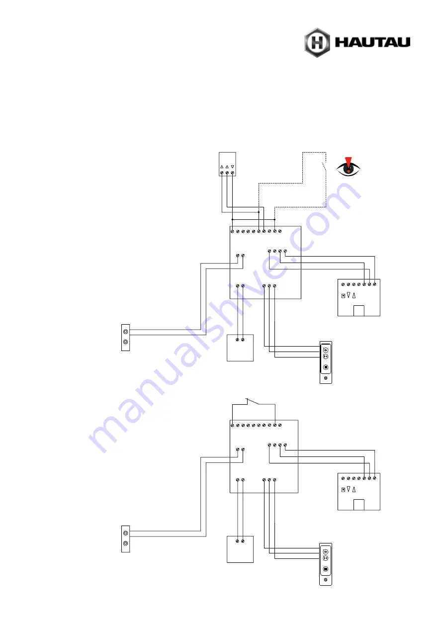
Electrical connection (continuation)
Connecting diagramm (examples)
Circuit board drive module
HS / S comfort drive
Control keypad
WLAN box
Key switch
Finger print sensor
Signal length: 0,5 ... 1 s
EMERGENCY STOP switch
Lift drive
contact delivery
Lift drive
contact delivery
Power supply 24 V DC
Power supply 24 V DC
red
red
br
own
brown
black
OPEN CL
OSE
black
Lift & Slide v WLAN box
with EMERGENCY STOP switch
Lift & Slide v WLAN box
without EMERGENCY STOP switch
in case of 1-button control
pushbutton, refer to
section ‘Connection
of 1-button control
pushbutton’
Control keypad
WLAN box
re
d
red
br
own
brown
black
black
Power
supply
HAUTAU bus
Control keypad
or
Power
supply
HAUTAU bus
Control keypad
Circuit board drive module
HS / S comfort drive
Lift drive
Lift drive
in case of 1-button control
pushbutton, refer to
section ‘Connection
of 1-button control
pushbutton’


