background image


AXIS4000


W

HEEL 

A

LIGNMENT 

S

YSTEM


HAWEKA Wheel Alignment –AXIS4000 


36 

Front axle measurement 


Turn angle 

9.7  Castor, KPI, relative steering angle and max. turn angle 

 
Measurement of the castor, KPI, relative steering angle and max. turn angle is carried out in one 
work step. The cameras must be switched on and each one pointed at the front reflector. If this is 
not the case, a corresponding instruction window will remind you to position the camera appropriate-
ly before measurement. 
 

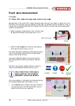
  Before beginning measurement, each camera must 

be aligned horizontally using a spirit level.

 (Fig. 59)


  Select the 

Turn angle

 menu point on the measure-

ment report overview screen. 

(Fig. 60)


The work steps that now follow are described by instruc-
tions in the program window and are simultaneously 
shown on the monitor screen. 
 
Two green LEDs also appear on the camera when 
measuring and when turning in whichever direction. 

(Fig. 59)


Symbols in the program window will tell you when to 
carry out individual steering movements.

 (Fig. 61)


WHILE EXECUTING A TURN ANGLE, 
MAKE SURE THAT THE STEERING  
MOVEMENT IS EVEN AND SMOOTH


Once the procedure is completed, the measured values 
recorded will appear after a brief pause. 

(Fig. 62)


The 

Continue

 button changes the program back to 

the overview screen for the selected axle and dis-
plays the ACTUAL value measured. 


(Fig. 62)


(Fig. 59)


Left/right         Straight            Stop       Finished 

(Fig. 61)


(Fig. 60)


LED for turn angle 
 

Summary of Contents for 924 000 010

Page 1: ...cles Translation of the original manual Kokenhorststraße 4 D 30938 Burgwedel Tel 49 0 5139 8996 0 Fax 49 0 5139 8996 222 www haweka com info haweka com Subject to technical amendment All rights reserved Duplication and copying in whole or in part are only allowed with written approval GEB 001 091 ...

Page 2: ......
Page 3: ...under Windows 18 6 3 Installing the FM transmitter 18 7 The AXIS4000 program 20 7 1 Setting up the software 20 7 2 Overview of the program settings screen 21 7 2 1 Customer data 21 7 2 2 Language 21 7 2 3 Interface 22 7 2 4 Camera symbol information 22 7 2 5 Default side of steering 23 7 2 6 Instructions 23 7 2 7 Data folder 23 7 2 8 Extended settings 24 7 2 9 System overview 24 7 2 10 Password En...

Page 4: ...up the reflector stands for articulated trailers 46 13 2 1 Setting up the reflector stands 47 13 3 Aligning the vehicle axle on the drawbar 48 13 4 Examining the trailer coupling ring in relation to the vehicle centre line 49 13 4 1 Attaching the reflector stand to the trailer coupling ring 49 13 4 2 Setting up the rear reflector stand 50 14 Vehicles with two steerable front axles 52 15 Taking int...

Page 5: ...tation The operator must in particular ensure that the system is used properly in accordance with these instructions the system is only operated when in proper working order these operating instructions are always legible complete and available where the system is in use the system is operated only by qualified and authorised persons who are familiar with these operating instructions personnel are...

Page 6: ...ows down the cause of the problem In all cases a visual check must be followed by axle measurement All these circumstances necessitate a suspension measurement with the aid of a wheel alignment sys tem Special tools are not the only thing important to measuring procedures the most important factors of suspension measurement still include the user s eyes hearing and technical skill 2 1 Suspension m...

Page 7: ...ward the narrowed end A Consequently wheels which both have a positive camber have a tendency to roll away from each other while wheels with negative camber roll towards each other Relative steering angle The relative steering angle is the difference in the angles between the front wheels and the vehicle centre line when the steering wheel is turned The angle A must be the same when steering to th...

Page 8: ... water This applies particularly during transport and storage of the complete wheel alignment system Ensure that the storage area is dry and free of dust Always store the equipment and the rechargeable battery packs for cameras in a charged state Length x Width x Height cm Transport weight kg gross AXIS4000 PRO 924 000 010 140 x 100 x 70 160 AXIS4000 PRO 924 000 013 120 x 80 x 90 160 AXIS4000 PRO ...

Page 9: ...EKA Wheel Alignment AXIS4000 9 4 Product description AXIS4000 Wheel Alignment System 924 000 010 030 050 Date 12 2017 Subject to technical amendment Version 5 1 Graphics HAWEKA AG D 30938 Burgwedel Reproduction in any form is not allowed ...

Page 10: ...lination Relative steering angle Max steering angle For the rear axle s Camber Toe Axle mismatch Axle inclination The AXIS4000 wheel alignment system enables measurements to be performed in a drive state i e the vehicle does not need to be lifted Other vehicle types can also be measured quickly and reliably with the appropriate accesso ries If the AXIS4000 wheel alignment system is not used in acc...

Page 11: ...haft from the 3 arm star The camera shaft is permanently mounted onto the 3 arm star It was adjusted and calibrated after mounting If e g after a fall you suspect that the camera shaft is not vertical to the 3 arm star anymore please contact your supplier Camera shaft Tensioning head 3 arm star Pro Clamp Knurled screw M8 x 40 quick change system Grab arm Magnetic feet 100 mm ...

Page 12: ... 10 Transmitting power 10 mW Camera Power supply Lithium Ion battery pack 18650 CF 2S1P 7 4 V 2250 mAh Operating time with fully charged batteries 10 h Charging unit Operating voltage 100 240 Volt Turning plates Load bearing capacity 6 to each 4 4 PC system requirements for the AXIS4000 Required operating system Windows XP Windows 7 8 1 10 Necessary minimum hardware requirements Processor Pentium ...

Page 13: ...heads Item No 924 001 000 6 pcs Magnetic holder 100 mm Item No 913 027 004 6 pcs quick change system Item No 913 027 006 2 pcs Tensioning head Item No 912e008 140 4 pcs Grab arms for trucks for aluminium rims Item No 912e008 303 6 pcs Special magnet for rear axle measurement 315 mm Item No 913 030 012 2 pcs Turning plates Item No 913 011 029 ...

Page 14: ...r plate for camera Item No 924 001 161 left Item No 924 001 162 right Item No 924 001 030 1 pc Floor plate for reflector Item No 924 001 029 1 pc Radio Server Unit incl USB cable Item No 924 001 160 1 pc Camera charging station Item No 924 001 034 4 pcs Reflectors Item No 924 001 025 4 pcs Tripod stands Item No 913 052 024 ...

Page 15: ...s Reflector stands Item No 913 052 081 2 pcs Magnetic feet for reflectors Item No 913 052 077 1 pc System stands only for 924 000 010 Item No 900 008 200 1 pc USB Stick 1 pc Operating instructions 1 pc Aluminium case Program AXIS4000 for cameras reflectors and transmitter ...

Page 16: ...Additional turning plates for second articulated vehicle axle Item No 924 000 002 1 Set of accessories for small transporter Item No 923 000 003 1 pc Frame gauge for holding the reflector stand on an omnibus or vehicle chassis Item No 923 001 043 1 Set of accessories for semi trailers and trailers Item No 923 000 001 1 pc King pin adapter 1 pc Coupling adapter 6 pc Magnetic holder 256 mm with quic...

Page 17: ...he software 6 1 Assembling the reflector stand One reflector stand comprises the following components a 1 x central section b 2 x outside sections with boreholes for the reflectors Pushing together of the two outer parts onto center part It should be ensured that the left and right parts have the same distance to the center part The number on the pawl must be equal on both sides The now assembled ...

Page 18: ...transmitter driver will be installed on the computer After installation remove the USB Stick from the PC The driver for the FM transmitter is usually added automatically to the system on your computer when the AXIS4000 program is installed If the FM transmitter is connected to a free USB port on the PC after installation the new hardware will be detected and integrated into the system If this func...

Page 19: ...re from a specific location and click on Next Fig 5 For the search option choose o Search removable storage device and click on Next Fig 6 The operating system has detected the driver and provides information about its compatibility with Win dows XP Read the information and continue with the installation To do this select o Continue installation Fig 7 After installation remove the USB Stick from t...

Page 20: ...e individual program points in just a few work steps with the support of help texts and graphic images You will always have enough information to feel confident with the program However before you start the first vehicle measurement you must carry out program settings for the most important parameters for individual use 7 1 Setting up the software Start the program Under Windows select START ALL P...

Page 21: ...ppear on the report Prerequisites for the image file Type BMP JPG GIF PNG The image size will be scaled Image files that are too small will be enlarged This will lead to a loss of image quality The smallest selected format should be within the range of 400 x 200 pixels at 72 dpi 7 2 2 Language Pressing the Select language button will give you the option of having the menu and all in structions in ...

Page 22: ...y the program using the Magnifier button Magnifier button The dialogue window is split into two areas The cameras found by the program but not yet connect ed are shown in the left area The right area shows the camera s that is are already connected wirelessly to the program The cameras and FM transmitter must be set to the same radio channel Serial numbers The camera serial numbers are displayed a...

Page 23: ...n which country it is used in you can set a vehicle steering side as the default steer ing side for examining the middle position of the steer ing gear Fig 19 7 2 6 Instructions Establishing the standard setting for showing or hiding work instructions during measurements Fig 20 The instruction window can be shown or hidden at any point in the program To do this click the Instructions button on the...

Page 24: ...ystem overview The system overview gives a list of components used by PC cameras FM transmitter and program versions This information is used by the service engineer as an overview of the system in the event of any faults Fig 23 7 2 10 Password Enter code This function is only used by our service per sonnel on site for diagnostic work on the sys tem This option enables you to carry out program spe...

Page 25: ...e to ensure that the rims and tyre sizes are all the same Check for adequate tyre tread Tyre wear Is there any noticeable uneven tyre wear Check the correct tyre inflation pressure Check for any play in the steering and wheel bearings Check the steering joints king pins Check the condition of the springs and shock absorbers Note the manufacturer s specifications for different loads in order to sim...

Page 26: ...that all 3 magnetic feet are the same distance from the centre of the stand Place the measurement heads with the magnets onto the cleaned rim flange There should be two magnets above the wheel centre and one below Fig 26 MAKE SURE THAT THE MEASUREMENT HEADS AND CAMERA SHAFTS ARE EACH FITTED CEN TRALLY IN LINE WITH THE CENTRAL HOLE OF THE RIM In the case of aluminium rims the two grab arms must eac...

Page 27: ...ick measure ment of camber castor KPI relative steering angle and max steering angle All other measurements can only be carried out when scale setup has been carried out be forehand Select Test floor inclination The vehicle must be measured on a level floor surface If the user suspects that the selected work surface is not on a horizontal plane between left and right vehicle sides the situation sh...

Page 28: ...d to the reflectors When a camera detects a reflector the symbol top right in the program changes and the process is con firmed by pressing the OK button on the corre sponding camera The program signals receipt of the measured values both visually with a green OK symbol and acoustical ly with a signal tone It does not matter in which sequence left right the reflectors are detected and confirmed by...

Page 29: ...NDS REMAIN STATION ARY ONLY THE REFLECTOR STAND IS MOVED As soon as the reflector stand is setup a centre line is shown in this area of the vehicle The program is now ready for the reflectors of the second reflector stand Now turn both cameras towards the front reflectors The bar on the screen displays a value again The front reflector stand must be moved to the side until the bar on the screen ch...

Page 30: ...ber must be adjusted on the vehicle when possible The following applies for adjustments IF THE CAMBER IS ADJUSTABLE ON THE VEHICLE THEN THIS IS ALWAYS ADJUSTED FIRST Click on the settings symbol to adjust the camber THE SETTINGS SYMBOL ONLY AP PEARS AFTER MEASURING THE ACTU AL VALUE While carrying out settings the current value for the left and right sides of the vehicle is displayed ana logue and...

Page 31: ... gear must be brought into a central posi tion before starting the measurement The corresponding camera must now be aligned to the front reflector Fig 44 Once the reflector has been detected confirm the process with the OK button on the camera The camera is now rotated by 180 degrees and aligned to the rear reflector Fig 45 Once the second reflector has been detected confirm the process again with...

Page 32: ...46 Check the steering middle position on the steering gear Fig 47 Carry out adjustments on the push rod until the de sired value is shown on the display During adjustments the current value is display con tinuously both analogue and digital for setting the NOMINAL value After adjustments are complete settings are con cluded with the Continue button The program changes back to the overview screen f...

Page 33: ...he program by a yellow light beam Fig 50 Values can be measured start ing on the left or right side of the vehicle this does not alter the measurement result After recording the measured values the single toe values measured for each vehicle side and the total toe will be immediately displayed Fig 51 The Continue button changes the program back to the overview screen for the selected axle and dis ...

Page 34: ...tion of adjusting the single toe On the selection screen for adjustments select Total toe A display appears for adjusting the NOMINAL value which always shows the current value of the total toe both analogue and digital in mm for the entire duration of adjustment Fig 53 If the toe value is needed in degrees then the display can be changed from mm to degrees Fig 54 On this topic please refer to Poi...

Page 35: ...ig 55 Adjusting the single toe for front axles with inde pendent wheel suspension On the selection screen for adjustments select Sin gle toe Fig 56 The single toe values for the left and right sides are shown on two displays for adjusting the NOMINAL value The current values and total toe are displayed analogue and digital in mm for the entire duration of adjustment Fig 57 If the toe value is need...

Page 36: ...menu point on the measure ment report overview screen Fig 60 The work steps that now follow are described by instruc tions in the program window and are simultaneously shown on the monitor screen Two green LEDs also appear on the camera when measuring and when turning in whichever direction Fig 59 Symbols in the program window will tell you when to carry out individual steering movements Fig 61 WH...

Page 37: ...t to the turn angle selection Before beginning measurement each camera must be aligned horizontally using a spirit level The turning lock can now be adjusted on the vehicle Fig 63 Usually the left turn angle is adjusted on the left side of the vehicle and the right turn angle is adjusted on the right side of the vehicle Use the Repeat measurement button to repeat this stage in the program until th...

Page 38: ... measure the ACTUAL camber val ue The camber value will then appear immediately in degrees and minutes The measured ACTUAL values must be compared to the required NOMINAL values If the ACTUAL values lie outside the tolerance range of the NOMINAL values then the camber must be adjusted on the vehicle when possible Click on the settings symbol to adjust the camber The following applies for adjustmen...

Page 39: ...g 69 The axle inclination is shown graphically in the program only from a value of 0 12 and axle mismatch is shown with a green arrow upwards of 1 mm and a red arrow upwards of 10 mm To adjust the toe and inclination click the adjust symbol next to the selection button Select the corresponding item for adjustment depend ing on the measurement result and vehicle axle Fig 70 10 2 1 Adjusting the toe...

Page 40: ... of the rear axle is displayed in de grees and minutes both analogue and digital for the entire duration of adjustment Fig 73 The Continue button changes the program back to the overview screen for the selected axle and dis plays the adjusted value in the AFTER column Now select another rear axle in the program on the measurement screen The example shows Axle 3 selection Fig 74 The program changes...

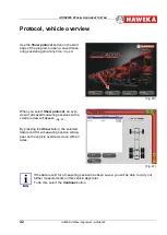
Page 41: ...l This view enables a com parison of measured data for all vehicle axles Fig 76 By selecting the Comment button Fig 77 you can enter special comments about the vehicle that will appear later on the report printout Use the Save button Fig 78 when work is finished to save the completed measurements Use the Print button Fig 79 to print out the recorded data as a protocol report on an installed printe...

Page 42: ...lect Show protocol an over view of all saved measuring sessions with a small preview will appear Fig 81 By pressing the Show button the selected data record for a measuring session will ap pear on the vehicle overview screen with all axles If the data record for a measuring session has been saved you will be able to carry out further measurements on this vehicle days later To do this select the Co...

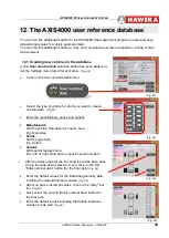
Page 43: ...u want to create nominal data Fig 83 Enter the manufacturer series and variant Manufacturer Add the vehicle manufacturer s name here E g Mercedes Series Add the type here E g Actros Variant Add special features here E g left or right hand drive or specific serial numbers After the axles types for the front and rear axles have been set via the drop down selection menu click on the first Enter nomin...

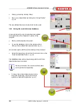
Page 44: ...e alignment as usual To use the database click on the scales symbol after you have added the measured data Fig 87 An overview opens with the vehicle data you have created Select the respective vehicle from the list and click on the Load nominal data button Fig 88 The NOMINAL data will be shown along with the ACTUAL data that has been recorded Via the print button the selected vehicle data can be p...

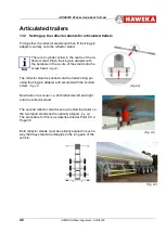
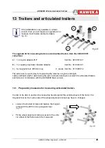
Page 45: ...029 012 The extension is used solely for measuring the total toe single toe left right camber left right and for determining the axle inclination and axle mismatch for articulated trailers and trailers in combination with the AXIS4000 basic version 13 1 Preparatory measures for measuring articulated trailers In order to be able to position the measuring heads against the vehicle wheels of the trai...

Page 46: ...re of the stand onto the screw head Fig 92 The reflector stand is pushed onto the trailer s king pin using the king pin adapter and secured with the knurled screw Fig 93 Now fasten it as usual i e both reflectors left and right onto the reflector stand The second reflector stand is set up behind the trailer on the two tripod stands and is optically aligned Fig 94 The procedure for this is as descr...

Page 47: ...e reflectors on the king pin Align the camera on the left and right to the reflec tors on the king pin Confirm positioning with the OK button on both camera casings Fig 96 Once both reflectors have been detected the program screen changes automatically and you will be asked to align both cameras to the rear reflectors The reflector stand must now be moved to the side until the display nearly reach...

Page 48: ...g axle Place the magnetic feet on both vehicle sides at the same position on the chassis Hang the reflectors on the right and left Place the cameras onto the wheel alignment clamp on each side of the vehicle and align against the re flectors on the magnetic feet Prepare the computer and select Trailer as vehicle type in the program Enter the rim size Fig 100 Select the Setup scales button Now the ...

Page 49: ...Now the reflector stand must be secured to the trailer coupling ring using the adapter Remove the magnetic feet from the chassis 13 4 1 Attaching the reflector stand to the trailer coupling ring Put together the reflector stand using the king pin adapter as described for the articulated trailer under Point 12 2 Fig 103 The coupling adapter is unscrewed Fig 104 and pulled up from below into the tra...

Page 50: ...y pressing the Continue button the program chang es to setup toe scale and a red vehicle centre line is shown in the upper area of the trailer 13 4 2 Setting up the rear reflector stand The reflector stand with reflectors is set up behind the trailer and is optically aligned Align both cameras against the rear reflectors The rear reflector must be moved to the side until the bar on the screen chan...

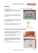
Page 51: ...selected in the pro gram and measurements are carried out Fig 110 Special features in the case of a tandem trailer with rigid drawbar Due to the special design of the tandem trailer with rigid drawbar the measuring procedure is to be carried out as for an articulated trailer Fig 111 The rigid drawbar on the tandem trailer is treated like the king pin on the articulated trailer The reflector stand ...

Page 52: ...e right vehicle side Both cameras are aligned against the rear reflec tors The wheels on the first steering axle stand in For ward direction this requires the steering gear to be brought into a central position Then select the Parallelism of steering axles button Fig 114 The program immediately detects the angle of the ax les in relation to each other and the measured value is displayed Fig 115 Pr...

Page 53: ...sured In front of the left wheel of the same axle fit the camera into the floor plate Fig 112 and align against the reflectors Turn the camera in the plate until the camera is aligned vertically with the aid of a spirit level Align the camera horizontally using the spirit level with the aid of the floor plate s setting screw Select the axle to be measured in the program window on the right side Th...

Page 54: ... value The left wheel is higher than the right when viewed in the direction of travel If you already know there is floor inclination as measurements are often carried out at the same place then the values can be entered manually and directly for each axle Fig 122 After measuring floor inclination for all axles press the Continue button The program changes back to the vehicle data screen for the se...

Page 55: ... rims box on the vehicle data overview screen and select the Continue button Fig 124 Run out compensation will now be carried out for the first wheel on the first axle on the following pro gram screen Follow the instructions on the left hand edge of the screen Compensation is conducted in three stages and is shown graphically Fig 125 Lower the vehicle back onto the turning plate Then carry out run...

Page 56: ...Always make sure that these components are used and maintained with the great est of care The protective cover in front of the camera lens must be cleaned with a dry soft cloth when necessary Never use alco hol or other liquids for cleaning Make sure that the reflectors are not scratched on the detecting side Scratched reflectors can lead to measurement errors Only use the charging unit supplied t...

Page 57: ...utton interface should be set to AUTO see Pnt 7 2 3 Try to establish a new con nection with another radio channel Install the USB driver which is on the USB Stick Pnt 6 3 Page 18 The camera does not detect any signal from the reflectors The reflectors are severely damaged or dirty Clean reflectors or replace with new ones if necessary Camera measurement head is not seated securely on the rim Dirty...

Page 58: ...AXIS4000 WHEEL ALIGNMENT SYSTEM HAWEKA Wheel Alignment AXIS4000 58 19 Appendix 19 1 Measurement report for vehicle measurement ...

Page 59: ...European norms EMC for radio units with a short range device SRD ETSI EN 301 489 03 ETSI EN 301 489 01 ETSI EN 300 220 1 ETSI EN 300 220 2 Broadband transmission systems 2 4 GHz ISM band ETSI EN 300 328 V2 1 1 Interference immunity and interference emissions EN 61326 1 Photobiological safety of lamps and lamp systems EN 62471 Exposure limits for artificial optical radiation BGI 5006 Protection IP5...

Page 60: ...HAWEKA AG Kokenhorststr 4 D 30938 Burgwedel 49 0 5139 8996 0 49 0 5139 8996 222 www haweka com Info haweka com ...

Reviews: