background image


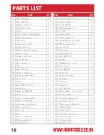
NO 

PART 

QTY 


NO 

PART 

QTY 

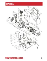
1  Bolt M6×25 

35  Spring washer 4 

2  Bolt M6×35 

36  Tooth washer 4 

3  Spring washer 6 

37  Screw M3×6 

4  Cylinder head 

38  Spring washer 3 

5  Circle 

39  Nut M3 

6  Valve plate subassembly 

40  Capacitance   

7  Cylinder seals 

41  Tooth washer 8 

8  Cylinder 

42  Discharge pipe D10mm 

9  Connection Stud 

43  Elbow connecter  

10  Screw M5×16 

44  Air filter 

11  Connecting rod cover   

45  Fan cover 

12  Piston ring 

46  Big washer 8 

13  Connecting rod 

47  Bolt M

×12 

14  Bolt M6×16 

48  Handle 

15  Big washer  6 

49  Thermal protector 

16  Fan 

50  Base board 

17  Bolt M4×20 

51  Bolt M8×25 

18  Spring washer 4 

52  Washer 8 

19  Bearing 6005-2RS 

53  Flange nut M8 

20  Pin 4x14 

54  6L tank  

21  Crank 

55  Absorber 

22  Bolt M8×35-left 

56  Washer 5 

23  Crankcase 

57  Bolt M5×25 

24  Bearing 6204-RS 

58  Drain valve 1/4  inch 

25  Rotor  

59  Quick coupler 

26  Stator subassembly 

60  Pressure gauge 40   

27  Bearing 6202-RS 

61  Regulate valve 

28  Corrugate washer 34 

62  Three way connecter 

29  Motor bracket 

63  Safety valve 

30  Circlip 

64  Power cord   

31  Fan 

65  Pressure gauge 50   

32  Bolt    M5×105 

66  Pressure switch 

33  Spring washer 5 

67  Release pipe 

34  Screw M4×10 

68  Checking valve 


PARTS LIST

10

PART

ITEM

QTY

PART

ITEM

QTY

Summary of Contents for HWKAC1

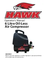
Page 1: ...6 Litre Oil Less Air Compressor Operator s Manual WARNING Before using this appliance read the Operator s manual and follow all its safety rules and instructions...

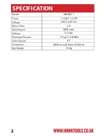
Page 2: ...SPECIFICATION ITEM 2 1 1 kW 1 5 HP 230 V 50 Hz HWKAC1 2 P 2850 rpm 5 7 cfm 115 psi 0 8 MPa 6 L 485mm x 265mm x550mm 16 kg...

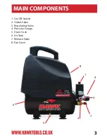
Page 3: ...8 1 4 3 7 2 5 6 MAIN COMPONENTS 3 1 On Off Switch 2 Outlet Valve 3 Regulating Valve 4 Pressure Gauge 5 Drain Cock 6 Air Tank 7 Release Valve 8 Fan Cover...

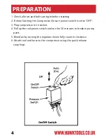
Page 4: ...mpressor Ensure power switch is set to OFF 3 Plug compressor in to socket 4 Pull up the red power switch and tun for 30 minutes to break in pump parts 5 Bleed air by turning the regulator know fully c...

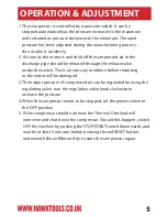
Page 5: ...ch This is a necessary condition before restarting or the motor will be damaged 3 The output pressure of compressed air can be regulated by using the regulating valve turn the regulation valve knob cl...

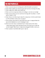
Page 6: ...an a 1 5mm section rated to 16A 6 Never disconnect the plug to stop the compressor Set the switch knob to off and follow instructions on page 5 7 If the release valve doesn t work when the motor is st...

Page 7: ...em Drain moisture from tank by opening drain cock located on the underside of the tank 4 Clean dust and dirt from the motor tank airlines pump and cooling fins while compressor is off 5 Unclip the air...

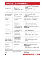
Page 8: ...ve with air in tank bleed tank Knocks rattles excessive vibration 1 Loose bolts tank not level 2 Defective bearing on eccentric or motor shaft 3 Cylinder or piston ring is worn or scored 1 Tighten bol...

Page 9: ...PARTS 9...

Page 10: ...1 49 Thermal protector 1 16 Fan 1 50 Base board 1 17 Bolt M4 20 1 51 Bolt M8 25 4 18 Spring washer 4 1 52 Washer 8 4 19 Bearing 6005 2RS 1 53 Flange nut M8 1 20 Pin 4x14 1 54 6L tank 1 21 Crank 1 55 A...

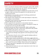
Page 11: ...in moving parts Always tie long hair back and wear suitable clothing 8 Clear the work area of all unnecessary tools debris and furniture 9 During operation the motor connections compressor body cylind...

Page 12: ...WARNING Before using this appliance read the Operator s manual and follow all its safety rules and instructions...

Reviews: