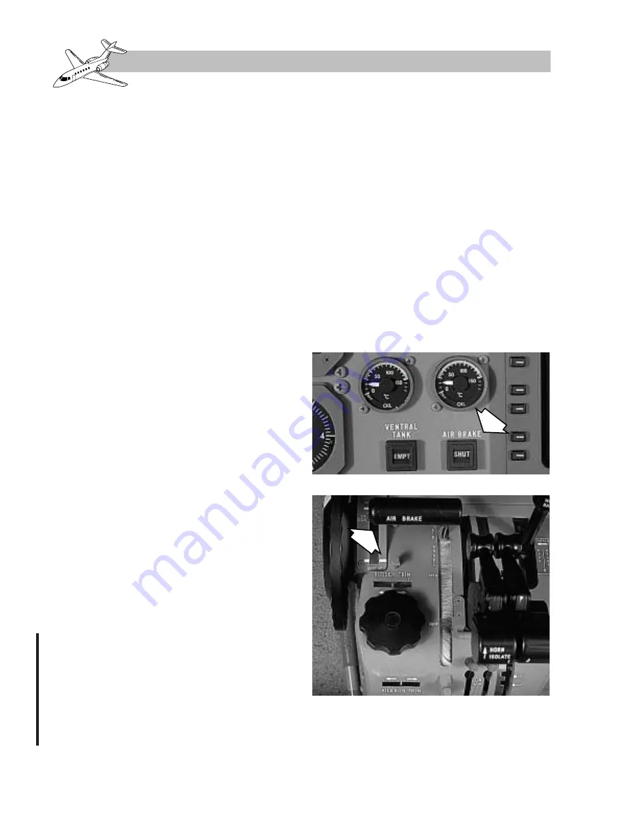
The airbrakes are controlled by an AIRBRAKE
selector lever located on the center control
pedestal (Figure 15-16). The lever moves ina
slot having a scale marked with three positions:
SHUT, OPEN, and DUMP.
The normal (flight and ground) operating range
is from the SHUT and fully OPEN selections.
Intermediate positions are obtained by leav-
ing the selector lever at the required setting
within the range.
A system of cables run from AIRBRAKE se-
lector lever to a hydraulic selector valve
mounted on each airbrake actuator. Main hy-
draulic system pressure is used to operate the
airbrakes through a hydraulic actuator in each
wing. To cater for control system failure, the
selector valve is biased to the SHUT position.
There is no service available from the auxil-
iary hydraulic system for the airbrakes should
the main hydraulic system fail.
Lift Dump
The AIRBRAKE selector is interconnected with
the input lever to the flap control unit. Selection
of airbrake between the SHUT and OPEN po-
sitions does not affect the flap position.
During the landing run with the flaps selected
to the 45° (land) position, lifting the AIR-
BRAKE selector and then moving it rearwards
into the DUMP position automatically lowers
the flaps from the 45° setting to 75°. It also
opens the airbrakes further to provide maxi-
mum drag.
Annunciations and Warnings
The position of the airbrakes is shown by an
AIR BRAKES OPEN-SHUT magnetic indi-
cator. The indicator is connected to two mi-
c r o s w i t c h e s , o n e o n e a c h a i r b r a ke . Wi t h
electrical power off, cross-hatching is dis-
played. With power on, the indicator shows
OPEN when either airbrake is in any position
other than fully closed. With both airbrakes
closed, SHUT is displayed.
A white AIR BRAKES annunciator is illumi-
nated on the MWS when the airbrakes are ex-
tended from the SHUT position (Figure 15-16).
A warning horn sounds if all of the following
conditions occur:
• The landing gear is down.
• Both thrust levers are advanced to more
than 40–60% N
1
power.
• The airbrakes are extended from the
SHUT position.
Electrical Power Supplies
The AIR BRAKES annunciator is powered
from PS2(a) busbar via circuit breaker AIR-
BRAKE (L2) on panel DA-D.
Revision 1
15-18
FOR TRAINING PURPOSES ONLY
HAWKER 800 XP
PILOT TRAINING MANUAL
FlightSafety
international
OPEN/SHUT ANNUNCIATOR
AIR BRAKE SELECTOR LEVER
Figure 15-16. Airbrake System Control
and Indication
Summary of Contents for 800 XP
Page 4: ......
Page 6: ......
Page 10: ......
Page 104: ......
Page 124: ......
Page 126: ......
Page 156: ......
Page 158: ......
Page 160: ......
Page 170: ......
Page 172: ......
Page 174: ......
Page 184: ......
Page 186: ......
Page 198: ......
Page 200: ......
Page 202: ......
Page 222: ......
Page 264: ......
Page 266: ......
Page 268: ......
Page 276: ......
Page 278: ......
Page 280: ......
Page 290: ......
Page 292: ......
Page 310: ......
Page 312: ......
Page 314: ......
Page 328: ......
Page 338: ......
Page 340: ......
Page 342: ......
Page 352: ......
Page 354: ......
Page 356: ......
Page 378: ......
Page 412: ......
Page 414: ......
Page 416: ......
Page 474: ......
Page 476: ......
Page 478: ......
Page 486: ......
Page 500: ......
Page 502: ......
Page 504: ......


