HAWKER 800 XP
PILOT TRAINING MANUAL
FlightSafety
international
position indicator is provided in the center in-
strument panel.
A rudder bias system is powered by engine
bleed air. This system automatically applies
opposite rudder to counteract the effect of
asymmetric thrust resulting from a single-en-
gine failure.
A stall warning (stick shake) and stall identifi-
cation system (stick push) is provided.
Internal gust locks are provided to lock the con-
trol surfaces when the aircraft is parked or
moored. The gust locks are rated for gusts of up
to 80 knots.
PRIMARY CONTROLS
AILERON CONTROL SYSTEM
Movement of the ram’s-horn type handwheel
on either control column operates the ailerons.
Each handwheel operates a lever at the bottom
of the column through chains and cables. A
connecting rod interconnects the levers of
each column. The left column lever is also
connected to a pulley drum. From the pulley
drum a combination of cables and tie-rods op-
erate a differential pulley in each wing. This
pulley is connected to the aileron by the levers
and links (Figure 15-1).
Each aileron control surface is fitted with a
mass balance weight to prevent flutter and a
horn balance to reduce the aerodynamic loads
felt by the pilot.
Primary stops are located at the left and right
aileron inboard hinges to limit the upward
range of movement. Secondary stops are lo-
cated at the bottom of each control column.
Aileron Geared and Trim Tabs
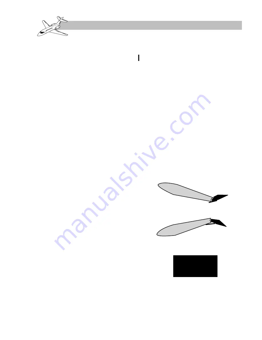
Each aileron has a servo-action geared tab
mounted on its trailing edge (Figure 15-2).
The tab is connected to the aileron by twin
connecting rods, and moves in the opposite
sense to the aileron lightening the aerody-
namic loads on the pilot’s handwheel.
The connecting rods for the left aileron tabs
are connected to a manually operated trim ac-
tuator. The trim actuator is connected by a
cable system to a trim handwheel mounted on
the center pedestal in the flight compartment.
Aileron Out-of-Trim Warning
A warning of the aileron being out of trim for
takeoff is given by the ELEV/AIL TRIM an-
nunciator illuminating (on the main MWS
panel) if the following conditions apply:
• Aircraft weight is on wheels.
• Both engine thrust levers are advanced
to more than 40–60% N
1
power.
Revision 1
15-3
FOR TRAINING PURPOSES ONLY
Figure 15-2. Aileron Geared Tab
Servo-Action
ELEV/AIL
TRIM
Summary of Contents for 800 XP
Page 4: ......
Page 6: ......
Page 10: ......
Page 104: ......
Page 124: ......
Page 126: ......
Page 156: ......
Page 158: ......
Page 160: ......
Page 170: ......
Page 172: ......
Page 174: ......
Page 184: ......
Page 186: ......
Page 198: ......
Page 200: ......
Page 202: ......
Page 222: ......
Page 264: ......
Page 266: ......
Page 268: ......
Page 276: ......
Page 278: ......
Page 280: ......
Page 290: ......
Page 292: ......
Page 310: ......
Page 312: ......
Page 314: ......
Page 328: ......
Page 338: ......
Page 340: ......
Page 342: ......
Page 352: ......
Page 354: ......
Page 356: ......
Page 378: ......
Page 412: ......
Page 414: ......
Page 416: ......
Page 474: ......
Page 476: ......
Page 478: ......
Page 486: ......
Page 500: ......
Page 502: ......
Page 504: ......


