background image

LIFE

PLUS

 MOD3


Owner’s Manual 

AM-HLPM3-OM 

Rev AB September 2019 


INSTALLATION 


WARNING: THE SHIPPING PALLET MUST BE REMOVED FOR PROPER AND SAFE 
OPERATION 

 
Location 

For maximum trouble-free service, choose a location which is free of excess moisture, dust and 
corrosive fumes. Also, avoid locations where temperatures are high or where liquids will drip on 
the charger. Follow charger warning label when mounting on or over a combustible surface. Do 
not obstruct the ventilating openings. 

 
Wall/Floor Mount Cabinet Chargers 

The charger must be permanently mounted in a vertical position. The lower part of the charger 
must be at least 12 inches from the charger below if installed above another charger, and the 
upper part 12 inches from the ceiling. The distance between two chargers must be no less than 
12 inches. Use the mounting kit supplied with the charger. See the Mounting Dimensions section 
at the end of this manual for proper Wall and Floor mounting. 
 

NOTE: 

Ambient temperature cannot exceed 113° F (45° C).


Electrical Connections 

To prevent failure of the charger, be sure it is connected to the correct line voltage. 
 

WARNING: MAKE SURE THE POWER TO THE CHARGER IS OFF AND THE BATTERY IS 
DISCONNECTED BEFORE CONNECTING THE INPUT POWER TO THE TERMINALS OF 
THE CHARGER. 


Connecting Input Power 

Connect  the  input  power  to  the  appropriate  terminals, 

including  ground

.  For  screw  type 

terminals,  torque  to  15  in.lbs.  Follow  your  local  and  National  Electric  Code  in  making  these 
connections. 
 

AC Circuit Protection 

The user must provide suitable branch circuit protection and a disconnect method from the AC 
power supply to the charger to allow for safe servicing. 
 

Breaker/Fuse Chart 


AC Amps 

(A) 

Breaker/Fuse size 

 (A) 

1 - 12 

15 

12.1 - 16 

20 

16.1 - 20 

25 

Summary of Contents for LIFEPLUS LPM3-48C-120C

Page 1: ...r 2019 Model S N AC Input Voltage Installed by Date IMPORTANT Read and understand your user s manual before installing operating or servicing this product DO NOT DESTROY THIS BOOK Battery Charger with Wireless Communications Owner s Manual LIFEPLUS MOD3 Models LPM3 Standard and Flex LPM3C CEC ...

Page 2: ...creen 14 Main Menu Display 14 Main Menu 14 System Setup 15 Date 15 Time 15 Language 15 Displayed Units 15 Energy Saver 15 Display Brightness 15 Network 15 Reset History 15 Enter Password 15 Change Password 16 USB 16 History Data 16 Save Setup Parameters 16 Load Setup Parameters 17 Load Control Firmware 17 Load Module Firmware 17 Charge Profile Configuration 17 Battery Capacity 17 Auto Capacity 17 ...

Page 3: ...ults 27 Modules 28 Module Status Display 28 Info 28 Module Information 28 Module LED Status 28 Mounting Dimensions 29 3 Bay Wall Mounting Dimensions 29 6 Bay Wall Mounting Dimensions 31 Maintenance and Service 33 Component Locations 34 Technical Specifications for 208 220 240V 36 Technical Specifications for 440V 39 Technical Specifications for 480V 43 Technical Specifications for 600V 46 Maintena...

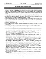
Page 4: ...atteries industrielles Avant tout emploi il est fortement conseillé de lire l ensemble des instructions recommandations et avertissements concernant le chargeur et la batterie 2 Ce chargeur a été conçu pour la charge des batteries industrielles type plomb acide dite ouverte Il ne peut pas être adapté pour les batteries étanches 3 Lisez toutes les condisnes d installation et d utilisation avant d e...

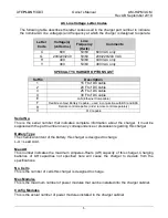
Page 5: ... Number and UL Model Number The UL Model Number specifies the characteristics of a full cabinet charger while the Part Number specifies the characteristics of the cabinet as configured plus all options The Part Number is required in any discussion or correspondence regarding this unit LPM3 48F 240YR Model type Phase for Standard or C for CEC Max DC Volts Cabinet Size Max DC Current Max DC V Input ...

Page 6: ...njunction with BSI and BSS R Remote control capable order remote control separately V PLC capable Serial No This is the serial number that indicates complete information about the charger It must be supplied with the part number on any correspondence or discussion regarding this charger Battery Type The chemical content of the battery this charger is designed to charge L A Lead Acid Max AH This nu...

Page 7: ...mps This is the Maximum AC current this charger will draw from AC power This charger must be connected to a branch circuit protection in accordance with the National Electrical Code NFPA70 and local codes AC breaker fuse values can be found on a decal outside the charger Max DC Amps This is the maximum DC current that this charger cabinet will deliver to a discharged battery when fully populated w...

Page 8: ...n two chargers must be no less than 12 inches Use the mounting kit supplied with the charger See the Mounting Dimensions section at the end of this manual for proper Wall and Floor mounting NOTE Ambient temperature cannot exceed 113 F 45 C Electrical Connections To prevent failure of the charger be sure it is connected to the correct line voltage WARNING MAKE SURE THE POWER TO THE CHARGER IS OFF A...

Page 9: ...rminated into the side of the battery connector and the black cable is terminated into the side of the connector The output polarity of the charger must be observed when connecting to the battery read warning above Improper connection will open the DC fuses in the power modules DANGER FAILURE TO GROUND THE CHARGER COULD LEAD TO FATAL ELECTRIC SHOCK Follow local and National Electric Code for groun...

Page 10: ... of the cell and amp hour rating as marked on the nameplate Auto Start Charge When a battery is connected to the charger the control board senses the voltage and after a 20 second delay the charger starts charging the battery automatically Charging Current Charging current is determined by the charger based on battery voltage and its state of charge Charging current declines automatically as batte...

Page 11: ...teries TPPL technology provides longer service life higher power density longer shelf life and fast recharge capabilities Flex Bloc Profile This charging profile allows charging of Flex bloc batteries at rates up to 0 7C Flex Standard Profile This charging profile allows charging of FLEX 2v cell batteries at rates up to 0 25C Flex Fast Profile This charging profile allows charging of FLEX 2v cell ...

Page 12: ...harge it during breaks lunch or any work stoppage time One time per day the battery must receive a full standard Ionic recharge The charger real time clock must be adjusted and set for this switch in charging profile to occur automatically at a predetermined time Sufficient time should be scheduled after the full charge to allow the battery to completely cool to ambient temperatures before use Not...

Page 13: ...s are available Ionic Gel Opportunity based on the configuration chosen by the operator If the charger is loaded with the Flex firmware then the selectable profiles are Flex Fast and Flex Bloc Furthermore equalization and compensation charges are integrated The LIFEPLUS MOD3 includes an adapter to communicate to a BBWC The BBWC is an advanced battery module that measures tracks and stores importan...

Page 14: ...n buttons Each navigation button corresponds with the rectangle located directly above it 3 STOP and START button Stop and restart battery charge 4 LED indicator Solid RED fault indicator Blinking RED charge stopped Solid YELLOW charging Solid GREEN charger idle Blinking GREEN charge complete 5 USB port Logs charge data updates firmware and saves setup parameters Menu Access 1 5 2 3 4 ...

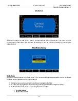
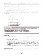
Page 15: ...xited voluntarily by pressing the Close button Main Menu Display Main Menu All menus are accessed from Main Menu The menus that require a password are not displayed until the correct password has been entered 1 Select a menu option using the Up Down navigation buttons 2 Display the highlighted menu screen by pressing the Select navigation button 3 Return to the main menu by pressing the Close butt...

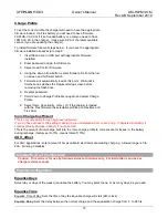
Page 16: ... minutes the display backlight and power modules will shut off to save energy Display Brightness Adjusts the brightness of the display screen Network This can only be accessed by entering a password If you don t know the password then a service technician will need to set this up Type Wired Wireless Select network type Charger IP Address Enter address Subnet Mask Enter Subnet Mask Gateway Address ...

Page 17: ...e able to change any passwords Change Tech Password Use this to change the main password Change Admin Password Use this to change the admin password erord USB History Data Enables the storage of charge History Data to a USB data storage device aka memory stick thumb drive To save charge history data 1 Insert the data storage device in the USB port on the front of the charger 2 Go to Setup USB Hist...

Page 18: ...or ionic All other profiles are manual all the time and will either use the battery Ah programmed into Battery Capacity or the value the charger reads from the BBWC When enabled in ionic the charger will automatically adjust to battery Ah sizes within the range it covers depending on number of modules installed Battery Temperature This parameter adjusts the regulation voltages on the charging prof...

Page 19: ... Select Ionic Opportunity or Gel Or if the charger is loaded with the Flex firmware the selectable profiles are Flex Bloc and Flex Fast Ionic Charge Coefficient This is only accessible through high level password If you do have access to this setting make sure you understand what you are doing If adjusted incorrectly it could eventually damage a battery if not corrected This is the amount of overc...

Page 20: ... Charge Blockout Block out Days Selects day or days of the week to block out charge One or more days may be selected or none Block Out Start Time Sets block out start time Block Out End Time Sets block out end time Conditional Charge Set conditional charge The charger will only charge if the battery has reached the limit of depth of discharge DoD of more than x For example if the user wants to cha...

Page 21: ...ize Module Type This can only be accessed by entering higher level password Select module type installed in charger Either 24 36 48 or 72 80 72 80 V Module Battery Voltage Charger Out of Service Leave this option selected if charging a 24 36 48 V battery Select 72 V or 80 V if charging a 72 V or 80 V battery DC Cable Setup DC Cable Length Selects the length of DC cables from the charger to the bat...

Page 22: ...y the charger serial number will need to be added Used when saving memos for keeping track of data Customer Asset Number Enter customer asset number Used when saving memos for keeping track of data Notice Regarding Cold Profile There is not a selectable profile for Cold This is because the LifePlus MOD3 charger will switch to the Cold profile automatically when using a Battery Boss WC on the batte...

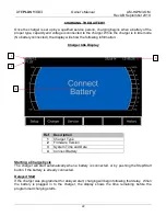
Page 23: ...llowing information Charger Idle Display S11 Starting a Charge Cycle The charger will start automatically when a battery is connected or by pushing the Stop Start button if the battery is already connected Delayed Start If the charger was programmed for delayed start charging will begin following that delay When the battery is plugged in to the charger the display shows the time remaining before t...

Page 24: ...ning for BBWC s This state is collecting addresses of any BBWC s within the adapter s range If any addresses are successfully collected the next state is Syncing see below If none were found the charger will display No BBWC s found and go straight to a charge cycle without a BBWC present Syncing Setting of three specific current values and measuring all BBWC s and running a match algorithm These s...

Page 25: ...ng information REF Description 1 Charge DC Voltage of battery alternating with charge Time AH and V C 2 Charge DC Current into battery 3 Battery S N reported by BBWC 4 Battery temperature 5 Charge time bar graph 6 Percent of charge bar graph 7 Programmed battery size in AH 8 BBWC link indicator 9 Charge profile 10 RFI transceiver is communicating with BBWC 1 8 5 6 7 9 4 3 2 10 ...

Page 26: ...and alternates between the battery voltage volt per cell and remaining time of the equalize charge Once equalize charge is complete the display background turns green and the displays shows Charge Complete indicating the battery is available for use If the battery remains plugged in and Refresh Charge has been enabled refresh charges will occur to maintain a full charge Automatic Equalize If an eq...

Page 27: ... will match the charger nameplate It must be supplied with the part number on any correspondence or discussion regarding this charger Asset No Assigned by the customer and programmed at the factory or by an authorized service personnel Connects Total number of times the charger has been connected to a battery Complete Equalizes Total number of equalizes normally terminated Complete Charges Total n...

Page 28: ...ected and the voltage is above 2 4 volts cell Can be reset if battery voltage is between 1 8 and 2 4 volts cell Charger Cell Size Exceeded Occurs when the battery cell size does not match the charger nameplate Check that the number of battery cells matches the charger nameplate Check Battery Occurs when the battery is overheating Allow the battery to cool Battery may need service Can be reset by d...

Page 29: ...dule 1 below this indicates the module is operating properly If is displayed under the module this indicates a fault Contact your servicing agent Info Displays details about each module installed Module LED Status The modules have LED indicators on the front These can be observed to determine the status of that particular module Flashing Green Module in Standby Solid Green Module in Use Red Module...

Page 30: ...LIFEPLUS MOD3 Owner s Manual AM HLPM3 OM Rev AB September 2019 29 MOUNTING DIMENSIONS 3 Bay Mounting Dimensions All dimensions are in inches ...

Page 31: ...LIFEPLUS MOD3 Owner s Manual AM HLPM3 OM Rev AB September 2019 30 All dimensions are in inches ...

Page 32: ...LIFEPLUS MOD3 Owner s Manual AM HLPM3 OM Rev AB September 2019 31 6 Bay Wall Mounting Dimensions All dimensions are in inches ...

Page 33: ...LIFEPLUS MOD3 Owner s Manual AM HLPM3 OM Rev AB September 2019 32 All dimensions are in inches ...

Page 34: ...LTAGES WITHIN THE BATTERY CHARGER CABINET ONLY QUALIFIED PERSONNEL SHOULD ATTEMPT TO ADJUST OR SERVICE THIS BATTERY CHARGER The charger requires a minimum of maintenance Connections and terminals should be kept clean and tight Follow recommended installation and make sure ventilation openings are not blocked MODULE FRONT ...

Page 35: ...FEPLUS MOD3 Owner s Manual AM HLPM3 OM Rev AB September 2019 34 COMPONENT LOCATIONS AC INPUT MODULE 3 SLOT MODULE 2 SLOT MODULE 1 SLOT DC OUTPUT Power Board AC FUSE 62 in lbs 62 in lbs Power Board DC FUSE ...

Page 36: ...LIFEPLUS MOD3 Owner s Manual AM HLPM3 OM Rev AB September 2019 35 Inside View of 3 Bay Cabinet Inside View of a 6 Bay Cabinet AC INPUT MODULE 6 SLOT MODULE 1 SLOT BACKPLANE FUSES ...

Page 37: ... LPM3 48C 120G 208 220 240 22 2 21 19 2 22 2 3 3 3 12 120 100 750 100 480 2 0 C 70 18 120 100 750 100 480 23 1 x 12 7 x 14 1 24 120 100 750 100 480 LPM3C48C 40G 208 220 240 7 4 7 0 6 4 22 2 3 1 3 12 40 100 250 100 160 2 0 C 54 18 40 100 250 100 160 23 1 x 12 7 x 14 1 24 40 100 250 100 160 LPM3C48C 80G 208 220 240 14 8 14 12 8 22 2 3 2 3 12 80 100 500 100 320 2 0 C 62 18 80 100 500 100 320 23 1 x 1...

Page 38: ...PM3C80C 75G 208 220 240 23 1 21 9 20 1 23 1 3 3 3 36 75 100 469 100 300 23 1 x 12 7 x 14 1 2 0 C 70 40 75 100 469 100 300 LPM3 48F 120G 208 220 240 22 2 21 19 2 44 4 3 3 6 12 120 100 750 100 480 3 0 F 86 18 120 100 750 100 480 23 17 x 21 x 13 77 24 120 100 750 100 480 LPM3 48F 160G 208 220 240 29 6 28 25 6 44 4 3 4 6 12 160 100 1000 100 640 3 0 F 94 18 160 100 1000 100 640 23 17 x 21 x 13 77 24 16...

Page 39: ... x 13 77 24 240 100 1500 100 960 LPM3 80F 75G 208 220 240 23 1 21 9 20 1 46 2 3 3 6 36 75 100 469 100 300 23 17 x 21 x 13 77 3 0 F 86 40 75 100 469 100 300 LPM3 80F 100G 208 220 240 30 8 29 2 26 8 46 2 3 4 6 36 100 100 625 100 400 23 17 x 21 x 13 77 3 0 F 94 40 100 100 625 100 400 LPM3 80F 125G 208 220 240 38 5 36 5 33 5 46 2 3 5 6 36 125 100 782 100 500 23 17 x 21 x 13 77 3 0 F 102 40 125 100 782...

Page 40: ...tunity Capacity Range Dimensions H x W x D inch Charger Cable AWG Cabinet Type Weight lbs Voltage Nominal Amp Draw Max Amps Phase Modules Cells Max Current A Capacity Range AH Bays Ah LPM3 48C 60H 440 5 3 15 9 3 1 3 12 70 100 438 100 280 2 0 C 54 18 65 100 407 100 260 23 1 x 12 7 x 14 1 24 60 100 375 100 240 LPM3 48C 120H 440 10 6 15 9 3 2 3 12 140 100 875 100 560 2 0 C 62 18 130 100 813 100 520 2...

Page 41: ...7 2 0 C 54 40 36 100 225 100 144 LPM3 80C 72H 440 10 6 15 9 3 2 3 36 80 100 500 100 320 23 17 x 21 x 13 77 2 0 C 62 40 72 100 450 100 288 LPM3 80C 108H 440 15 9 15 9 3 3 3 36 120 100 750 100 480 23 17 x 21 x 13 77 2 0 C 70 40 108 100 675 100 432 LPM3C80C 36H 440 5 3 15 9 3 1 3 36 40 100 250 100 160 23 17 x 21 x 13 77 2 0 C 54 40 36 100 225 100 144 LPM3C80C 72H 440 10 6 15 9 3 2 3 36 80 100 500 100...

Page 42: ...00 840 23 17 x 21 x 13 77 3 0 F 86 18 195 100 1219 100 780 24 180 100 1125 100 720 LPM3C48F 240H 440 21 2 31 8 3 4 6 12 280 100 1750 100 1120 23 17 x 21 x 13 77 3 0 F 94 18 260 100 1625 100 1040 24 240 100 1500 100 960 LPM3C48F 300H 440 26 5 31 8 3 5 6 12 320 100 2000 100 1280 23 17 x 21 x 13 77 3 0 F 102 18 320 100 2000 100 1280 24 300 100 1875 100 1200 LPM3C48F 320H 440 31 8 31 8 3 6 6 12 320 10...

Page 43: ... 3 6 6 36 240 100 1500 100 960 23 17 x 21 x 13 77 3 0 F 110 40 216 100 1350 100 864 LPM3C80F 108H 440 15 9 31 8 3 3 6 36 120 100 750 100 480 23 17 x 21 x 13 77 3 0 F 86 40 108 100 675 100 432 LPM3C80F 144H 440 21 2 31 8 3 4 6 36 160 100 1000 100 640 23 17 x 21 x 13 77 3 0 F 94 40 144 100 900 100 576 LPM3C80F 180H 440 26 5 31 8 3 5 6 36 200 100 1250 100 800 23 17 x 21 x 13 77 3 0 F 102 40 180 100 1...

Page 44: ...640 2 0 C 62 18 160 100 1000 100 640 23 1 x 12 7 x 14 1 24 120 100 750 100 480 LPM3 48C 180Y 480 14 4 14 4 3 3 3 12 240 100 1500 100 960 2 0 C 70 18 240 100 1500 100 960 23 1 x 12 7 x 14 1 24 180 100 1125 100 720 LPM3C48C 60Y 480 4 8 14 4 3 1 3 12 80 100 500 100 320 2 0 C 54 18 80 100 500 100 320 23 1 x 12 7 x 14 1 24 60 100 375 100 240 LPM3C48C 120Y 480 9 6 14 4 3 2 3 12 160 100 1000 100 640 2 0 ...

Page 45: ... C 54 40 36 100 225 100 144 LPM3C80C 72Y 480 9 6 14 4 3 2 3 36 80 100 500 100 320 23 17 x 21 x 13 77 2 0 C 62 40 72 100 450 100 288 LPM3C80C 108Y 480 14 4 14 4 3 3 3 36 120 100 750 100 480 23 17 x 21 x 13 77 2 0 C 70 40 108 100 675 100 432 LPM3 48F 180Y 480 14 4 28 8 3 3 6 12 240 100 1500 100 960 23 17 x 21 x 13 77 3 0 F 86 18 240 100 1500 100 960 24 180 100 1125 100 720 LPM3 48F 240Y 480 19 2 28 ...

Page 46: ... 102 18 320 100 2000 100 1280 24 300 100 1875 100 1200 LPM3C48F 320Y 480 28 8 28 8 3 6 6 12 320 100 2000 100 1280 23 17 x 21 x 13 77 3 0 F 110 18 320 100 2000 100 1280 24 320 100 2000 100 1280 LPM3 80F 108Y 480 14 4 28 8 3 3 6 36 120 100 750 100 480 23 17 x 21 x 13 77 3 0 F 86 40 108 100 675 100 432 LPM3 80F 144Y 480 19 2 28 8 3 4 6 36 160 100 1000 100 640 23 17 x 21 x 13 77 3 0 F 94 40 144 100 90...

Page 47: ...del Number AC Input DC Output 8 hour Opportunity Capacity Range Dimensions H x W x D inch Charger Cable AWG Cabinet Type Weight lbs Voltage Nominal Amp Draw Max Amps Phase Modules Cells Max Current A Capacity Range AH Bays Ah LPM3 48C 60C 600 3 8 11 4 3 1 3 12 80 100 500 100 320 2 0 C 54 18 80 100 500 100 320 23 1 x 12 7 x 14 1 24 60 100 375 100 240 LPM3 48C 120C 600 7 6 11 4 3 2 3 12 160 100 1000...

Page 48: ...17 x 21 x 13 77 3 0 F 110 18 320 100 2000 100 1280 24 320 100 2000 100 1280 LPM3 80C 108C 600 3 8 11 4 3 1 3 36 40 100 250 100 160 23 17 x 21 x 13 77 2 0 C 54 40 36 100 225 100 144 LPM3 80C 144C 600 7 6 11 4 3 2 3 36 80 100 500 100 320 23 17 x 21 x 13 77 2 0 C 62 40 72 100 450 100 288 LPM3 80C 180C 600 11 4 11 4 3 3 3 36 120 100 750 100 480 23 17 x 21 x 13 77 2 0 C 70 40 108 100 675 100 432 LPM3 8...

Page 49: ...IFEPLUS MOD3 Owner s Manual AM HLPM3 OM Rev AB September 2019 48 MAINTENANCE LOG 1 Modifications to Factory Settings Date Variable Change Service Technician 2 Service Date Description Service Technician ...

Page 50: ...700 Fax 423 238 6060 www hawkerpowersource com AM HLPM3 OM Rev AB September 2019 2019 HAWKER All rights reserved Trademarks and logos are the property of HAWKER except for the BL and UL logos which are not the property of HAWKER Subject to revisions without prior notice E O E ...

Reviews: