background image

PTO

 MOD

3


Owner’s Manual 

AM-HPTOM3-OM 

Rev AB February 2020


IMPORTANT SAFETY INSTRUCTIONS 


WARNING:  THE  SHIPPING  PALLET  MUST  BE  REMOVED  FOR  PROPER  AND  SAFE 
OPERATION. 

 
1.  This  manual  contains  important  safety  and  operating  instructions.  Before  using  the  battery  charger,  read  all 

instructions, 

CAUTIONs

 and 

WARNINGs

 on the battery charger, the battery and the product using the battery. 

2.  This battery charger is designed to charge flooded and sealed lead-acid batteries. Read and understand all setup 

and operating instructions before using the battery charger to prevent damage to the battery and to the charger. 

3. 

Do not

 touch non-insulated parts of the output connector or the battery terminals to prevent electrical shock. 

4.  During charge, batteries produce hydrogen gas which can explode if ignited. Never smoke, use an open flame, or 

create sparks in the vicinity of the battery.  Ventilate well when the battery is in an enclosed space. 

5. 

Do not 

connect or disconnect the battery plug while the battery is charging. Doing so will cause arcing and burning 

of the connector resulting in charger damage or battery explosion. 

6.  Lead-acid batteries contain sulfuric acid which causes burns. 

Do not

 get in eyes, on skin, or on clothing.  In cases 

of contact with eyes, flush immediately with clean water for 15 minutes. Seek medical attention immediately. 

7.  Only factory qualified personnel can service this equipment. De-energize all AC and DC power connections before 

servicing the charger. 

8.  The charger is 

not

 for outdoor use. 

9.  Do not expose the charger to moisture. Operating 

conditions

 should be 32º to 113º F (0º to 45º C); 0 to 70% relative 

humidity. 

10.  Do not operate the charger if it has been dropped, received a sharp hit, or otherwise damaged in any way.  
11.  For continued protection and to reduce the risk of fire, install chargers on a floor of non-combustible material such 

as stone, brick, or grounded metal. 


Summary of Contents for PTO MOD3

Page 1: ...Flex For parts sales call toll free 1 800 409 8895 and for charger technical support troubleshooting and service call 1 800 251 6560 AM HPTOM3 OM Rev AB February 2020 Model S N AC Input Voltage Instal...

Page 2: ...er Password 14 Change Password 14 USB 15 Memo Data 15 Save Setup Params 15 Load Setup Params 15 Load Control FW 15 Load Module FW 15 Charger Prof Config 15 Battery Cells 15 Battery Capacity 15 Battery...

Page 3: ...n the vicinity of the battery Ventilate well when the battery is in an enclosed space 5 Do not connect or disconnect the battery plug while the battery is charging Doing so will cause arcing and burni...

Page 4: ...field Part Number and UL Model Number The UL Model Number specifies the characteristics of a full cabinet charger while the Part Number specifies the characteristics of the cabinet as configured plus...

Page 5: ...ction with BSI and BSS R Remote control capable order remote control separately V PLC capable Serial No This is the serial number that indicates complete information about the charger It must be suppl...

Page 6: ...This is the Maximum AC current this charger will draw from AC power This charger must be connected to a branch circuit protection in accordance with the National Electrical Code NFPA70 and local codes...

Page 7: ...rgers must be no less than 12 inches Use the mounting kit supplied with the charger See the Mounting Dimensions section at the end of this manual for proper Wall and Floor mounting NOTE Ambient temper...

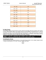
Page 8: ...into the side of the battery connector and the black cable is terminated into the side of the connector The output polarity of the charger must be observed when connecting to the battery read warning...

Page 9: ...nd amp hour rating as marked on the nameplate Auto Start Charge When a battery is connected to the charger the control board senses the voltage and after a 20 second delay the charger starts charging...

Page 10: ...ng Equalization charging performed after normal charging balances the electrolyte densities in the battery s cells Opportunity Profile The OPPOR charge profile is used when opportunity charging is des...

Page 11: ...sal Serial Bus OPERATING INSTRUCTIONS The PTO MOD3 series of chargers are compatible with batteries at 24 36 48 volts or 72 80 volts depending on the version supplied Battery voltage and Amp hour size...

Page 12: ...s Stop and restart battery charge 5 Navigate RIGHT EQUALIZE button Scroll right Start equalize or desulfation 6 Navigation DOWN button Navigate menus Change values 7 Navigation LEFT ESC button Enter M...

Page 13: ...he current menu is automatically exited after two minutes of inactivity or can be exited voluntarily by pressing the ESC button 1 Select a menu option using the Up Down buttons The selected menu will...

Page 14: ...ord is entered to gain access to service level menus by authorized Hawker service personnel 1 Use the Up Down buttons to select the correct alphanumeric character 2 Use the Left Right buttons to move...

Page 15: ...e aka memory stick thumb drive Load Setup Paramrs Enables the uploading of the charger Setup Parameters from a USB data storage device aka memory stick thumb drive Load Control FW Enables the updating...

Page 16: ...Enter password and go to USB menu 3 Select Load Control FW 4 Using the down arrow button select firmware file from the list on screen and hit Select button 5 Firmware will automatically load at this p...

Page 17: ...conditional charge The charger will only commence the charge if the battery has reached the limit of depth of discharge DoD of more than x For example if the user wants to charge the battery only if...

Page 18: ...BSI or Electrovalve If using one of these charger options that option must be enabled I O Test is used to test the functionality of each option Use the up and down buttons to highlight the correct I O...

Page 19: ...will start automatically when a battery is connected or by pushing the Stop Start button if the battery is already connected Delayed Start If the charger is programmed for delayed start charging will...

Page 20: ...oments into the effective charge the display will begin alternating between the following charging information Ref Description 1 Charger Type 2 Firmware Version 3 Charge Profile 4 System Time and Date...

Page 21: ...n an optimal charge The battery is now ready for use Push the ON OFF button before unplugging the battery End of Charge with Equalization An Equalize charge can be started manually or automatically Ma...

Page 22: ...y will be available when the green LED comes back on and the display shows Charge Complete The battery is now ready for use If the battery remains plugged in and Refresh charge has been enabled refres...

Page 23: ...l number of times a battery was disconnected during the life of charger DF1 etc Number of faults recorded over the life of the charger see fault codes Modules The module status is listed in ascending...

Page 24: ...rder one being the most recent charge cycle Memos are stored for one year from the date recorded Displaying a Charge Cycle Proceed as follows 1 Select a record Memo x using the buttons 2 Display the f...

Page 25: ...ing Battery charge gauges and lift interrupts may need calibration DF5 Start time with full start rate current applied or charge cycle taper and finish time is exceeded Check the battery temperature C...

Page 26: ...PTO MOD3 Owner s Manual AM HPTOM3 OM Rev AB February 2020 26 3 Bay Mounting Dimensions All dimensions are in inches...

Page 27: ...PTO MOD3 Owner s Manual AM HPTOM3 OM Rev AB February 2020 27 6 Bay Mounting Dimensions All dimensions are in inches...

Page 28: ...PTO MOD3 Owner s Manual AM HPTOM3 OM Rev AB February 2020 28 All dimensions are in inches...

Page 29: ...PTO MOD3 Owner s Manual AM HPTOM3 OM Rev AB February 2020 29 All dimensions are in inches...

Page 30: ...NEL SHOULD ATTEMPT TO ADJUST OR SERVICE THIS BATTERY CHARGER The charger requires a minimum of maintenance Connections and terminals should be kept clean and tight Follow recommended installation and...

Page 31: ...PTO MOD3 Owner s Manual AM HPTOM3 OM Rev AB February 2020 31 COMPONENT LOCATIONS AC INPUT MODULE 3 SLOT MODULE 2 SLOT MODULE 1 SLOT DC OUTPUT BACKPLANE FUSES 20 in lb 20 in lb...

Page 32: ...PTO MOD3 Owner s Manual AM HPTOM3 OM Rev AB February 2020 32 Inside View of Cabinet Inside View of a 6 Bay Cabinet AC INPUT MODULE 6 SLOT MODULE 1 SLOT BACKPLANE FUSES...

Page 33: ...100 640 23 1 x 12 7 x 14 1 62 PTOM1 48C 100Y 480 14 2 21 3 1 2 3 18 100 100 625 100 400 2 0 C 24 100 100 625 100 400 PTOM1 24C 240Y 480 17 4 17 4 1 3 3 12 240 100 1500 100 960 23 1 x 12 7 x 14 1 70 P...

Page 34: ...0 23 17 x 21 x 13 77 3 0 F 102 24 250 100 1563 100 1000 PTOM1 48F 300Y 480 42 6 42 6 1 6 6 18 300 100 1875 100 1200 23 17 x 21 x 13 77 3 0 F 110 24 300 100 1875 100 1200 Technical Specifications for 2...

Page 35: ...80 100 500 100 320 PTOM3C48C 120G 208 220 240 22 2 21 19 2 22 2 3 3 3 12 120 100 750 100 480 2 0 C 70 18 120 100 750 100 480 23 1 x 12 7 x 14 1 24 120 100 750 100 480 PTOM3 80C 25G 208 220 240 7 7 7 3...

Page 36: ...100 500 100 320 PTOM3 48F 120G 208 220 240 22 2 21 19 2 44 4 3 3 6 12 120 100 750 100 480 3 0 F 86 18 120 100 750 100 480 23 17 x 21 x 13 77 24 120 100 750 100 480 PTOM3 48F 160G 208 220 240 29 6 28...

Page 37: ...220 240 29 6 28 25 6 44 4 3 4 6 12 160 100 1000 100 640 3 0 F 94 18 160 100 1000 100 640 23 17 x 21 x 13 77 24 160 100 1000 100 640 PTOM3C48F 200G 208 220 240 37 35 32 44 4 3 5 6 12 200 100 1250 100 8...

Page 38: ...100 600 23 17 x 21 x 13 77 3 0 F 110 40 150 100 940 100 600 PTOM3C80F 25G 208 220 240 7 7 7 3 6 7 46 2 3 1 6 36 25 100 155 100 100 23 17 x 21 x 13 77 3 0 F 70 40 25 100 155 100 100 PTOM3C80F 50G 208 2...

Page 39: ...560 2 0 C 62 18 130 100 815 100 520 23 1 x 12 7 x 14 1 24 120 100 750 100 480 PTOM3 48C 180H 440 15 9 15 9 3 3 3 12 210 100 1315 100 840 2 0 C 70 18 195 100 1220 100 780 23 1 x 12 7 x 14 1 24 180 100...

Page 40: ...2 0 C 54 40 36 100 225 100 144 PTOM3C80C 72H 440 10 6 15 9 3 2 3 36 80 100 500 100 320 23 1 x 12 7 x 14 1 2 0 C 62 40 72 100 450 100 288 PTOM3C80C 108H 440 15 9 15 9 3 3 3 36 120 100 750 100 480 23 1...

Page 41: ...31 8 3 1 6 12 70 100 440 100 280 3 0 F 70 18 65 100 405 100 260 23 17 x 21 x 13 77 24 60 100 375 100 240 PTOM3C48F 120H 440 10 6 31 8 3 2 6 12 140 100 875 100 560 3 0 F 78 18 130 100 815 100 520 23 1...

Page 42: ...144 100 900 100 576 PTOM3 80F 180H 440 26 5 31 8 3 5 6 36 200 100 1250 100 800 23 17 x 21 x 13 77 3 0 F 102 40 180 100 1125 100 720 PTOM3 80F 216H 440 31 8 31 8 3 6 6 36 240 100 1500 100 960 23 17 x...

Page 43: ...1 24 120 100 750 100 480 PTOM3 48C 180Y 480 14 4 14 4 3 3 3 12 240 100 1500 100 960 2 0 C 70 18 240 100 1500 100 960 23 1 x 12 7 x 14 1 24 180 100 1125 100 720 PTOM3C48C 60Y 480 4 8 14 4 3 1 3 12 80...

Page 44: ...100 450 100 288 PTOM3C80C 108Y 480 14 4 14 4 3 3 3 36 120 100 750 100 480 23 1 x 12 7 x 14 1 2 0 C 70 40 108 100 675 100 432 PTOM3 48F 60Y 480 4 8 28 8 3 1 6 12 80 100 500 100 320 3 0 F 70 18 80 100 5...

Page 45: ...480 9 6 28 8 3 2 6 12 160 100 1000 100 640 3 0 F 78 18 160 100 1000 100 640 23 17 x 21 x 13 77 24 120 100 750 100 480 PTOM3C48F 180Y 480 14 4 28 8 3 3 6 12 240 100 1500 100 960 23 17 x 21 x 13 77 3 0...

Page 46: ...5 6 36 200 100 1250 100 800 23 17 x 21 x 13 77 3 0 F 102 40 180 100 1125 100 720 PTOM3 80F 216Y 480 28 8 28 8 3 6 6 36 240 100 1500 100 960 23 17 x 21 x 13 77 3 0 F 110 40 216 100 1350 100 864 PTOM3C8...

Page 47: ...160 100 1000 100 640 23 1 x 12 7 x 14 1 24 120 100 750 100 480 PTOM3 48C 180C 600 11 4 11 4 3 3 3 12 240 100 1500 100 960 2 0 C 70 18 240 100 1500 100 960 23 1 x 12 7 x 14 1 24 180 100 1125 100 720 PT...

Page 48: ...44 PTOM3 80C 72C 600 7 6 11 4 3 2 3 36 80 100 500 100 320 23 1 x 12 7 x 14 1 2 0 C 62 40 72 100 450 100 288 PTOM3 80C 108C 600 11 4 11 4 3 3 3 36 120 100 750 100 480 23 1 x 12 7 x 14 1 2 0 C 70 40 108...

Page 49: ...PTO MOD3 Owner s Manual AM HPTOM3 OM Rev AB February 2020 49 MAINTENANCE LOG 1 Modifications to Factory Settings Date Variable Change Service Technician 2 Service Date Description Service Technician...

Page 50: ...s and logos are the property of Hawker except for the BL and UL logos which are not the property of Hawker Subject to revisions without prior notice E O E P O Box 808 9404 Ooltewah Industrial Drive Oo...

Reviews: