Technical Support | Toll free US & Canada: 1.888.202.3344 | Email: techsupport@hawkingtech.com
www.hawkingtech.com
Technical Support: 1.888.202.3344
© 2013 Hawking Technologies, Inc. All rights reserved.
Mounting Options
WALL MOUNT INSTALLATION
POLE MOUNT INSTALLATION
SPECIFICATIONS
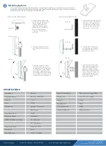
Once you have determined the appropriate location for your antenna (Step 2), choose how you would like to mount it. The antenna kit
includes both a pole mounting option and a wall mounting option. Please being both options by attaching an “L-Bracket” to the back of
the antennas with four “M6 Nuts” as detailed in the image to the right.
A. Examine the aerial view of the
antenna a pole to the left. Using
the two included “U-Bracket”
included in the antenna kit,
thread them around the pole,
through the two “Pole Bracket
Brace” and the antenna’s
“L-Bracket”. Secure with four
“M-6 Nuts”.
B. Take note of the extra holes in
the “L-Bracket” and proceed to
Part C.
A. Examine the aerial view of the wall
to the left. Using a Screw Driver or
Drill, mount the “L-Bracket” not
attached to your antenna to your
wall with the four included “M-4
Wall Anchor” and “M-4 Screw”.
B. Next attach the “L-Bracket” on
your antenna to the “L-Bracket”
on the wall with the four “M-6
Bolt” and “M-6 Screw”.
C. Adjust the angle of your direc-
tional antenna according to your
network environment. Simply insert
the “U-Brackets” into the different
holes on the “L-Bracket” until you
have reached the desired mounting
angle. Tighten the “M-6 Nuts” with
a wrench to ensure a lasting hold.
C. Adjust the angle of your direc-
tional antenna according to your
network environment. Simply
thread the “M-6 Bolt” through a
different set of holes and secure
with an “M-6 Nut” until you have
reached the desired mounting
angle. Tighten with a wrench to
ensure a lasting hold.
aerial view
aerial view
side view
aerial view
Connector
Brass
Pole Diameter
0.9 to 1.8 inches
Operating Temp
-40°F to 149°F
40° @H-plane
HPBW (3dB Beam Width)
25° @E-plane
Radiation Pattern
Directional
Front/Back Ratio
15dBi
Dual Linear
Polarization
Vertical / Horizontal
Gain
14dBi
V.S.W.R.
< 2.0
Frequency Range
2.4GHz - 2.435GHz
Impedance
50ohm
Insulator Material
Teflon or Delrin
Contact Material
Metal
Body Material
Plastic
Weight
3 Lbs
Dimensions
14.6 x 9.1 x 2.1 inches
Rated Wind Velocity
50m/s @ mount height 40m
side view
side view


