9
3. INSTALLATION AND CONNECTION
3.7 Water Flow Setting
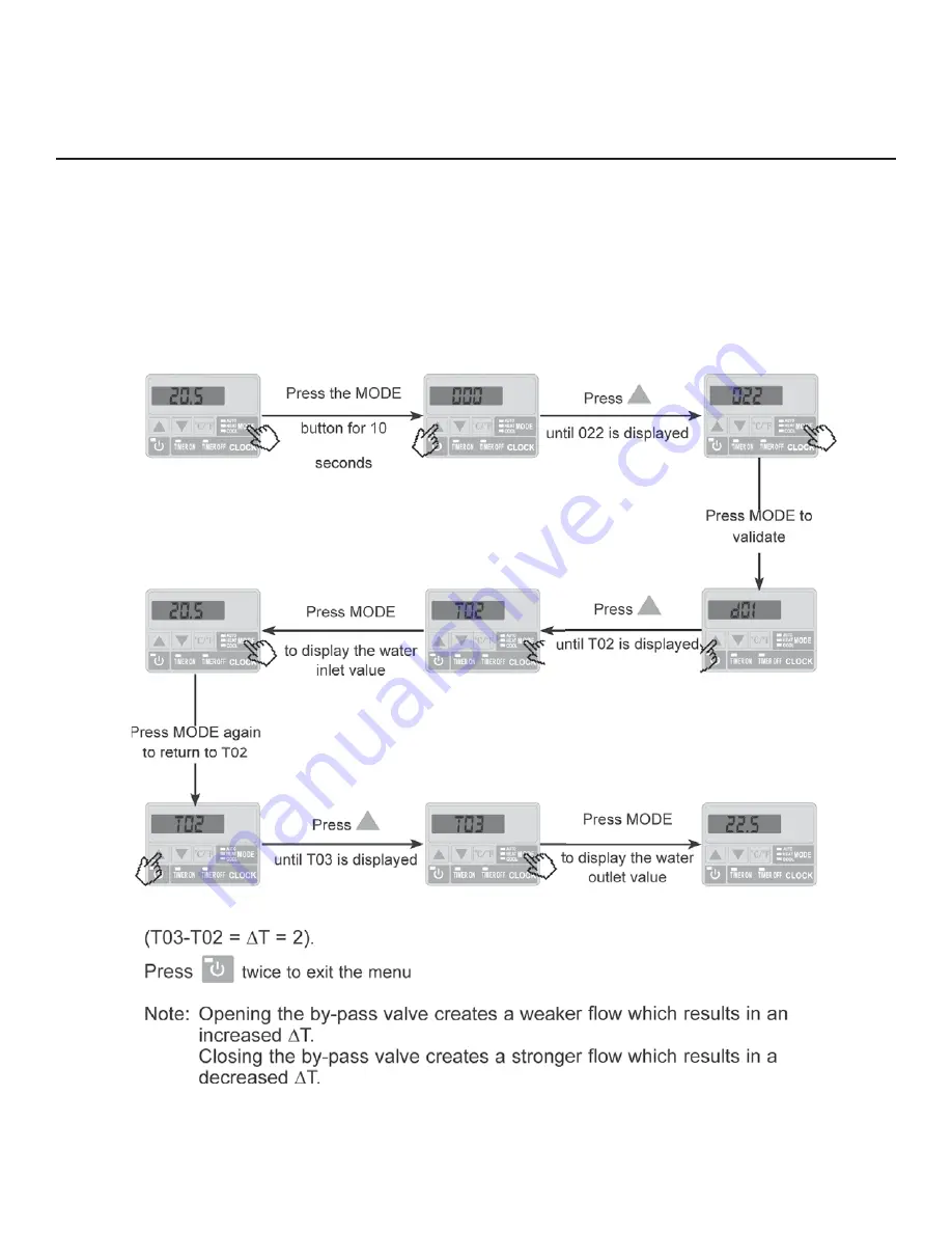
While the heat pump is running and the water inlet and outlet valves are open, adjust the by-
pass valve to obtain a difference of 2ºC between the water inflow and outflow temperatures (see
Functional Diagram Section 3.1). You can check the setting by viewing the inflow (T02)/outflow
(T03) temperatures directly on the control panel by following the procedure below.
Then adjust the by-pass to obtain a difference of 2ºC between T03 and T02
Summary of Contents for HP40A
Page 6: ...4 2 SPECIFICATIONS 2 2 Dimensions mm inches for the Swimming Pool Heat Pump Unit Model HP80A...
Page 7: ...5 3 INSTALLATION AND CONNECTION 3 1 Installation Illustration...
Page 12: ...10 4 USER INTERFACE 4 1 Overview...
Page 14: ...12 4 USER INTERFACE continued 4 2 Setting the Clock 4 3 Setting the Timer Function...
Page 15: ...13 4 USER INTERFACE continued 4 4 Choice of Operating Mode Heating Cooling or Automatic...
Page 17: ...15 4 USER INTERFACE continued 4 8 Parameter Table...
Page 19: ...17 5 MAINTENANCE AND INSPECTION 5 3 Winterization...
Page 20: ...18 6 APPENDIX 6 1 Connection of PCB Illustration...
Page 21: ...19 6 APPENDIX 6 2 Wiring Diagram HP40A...
Page 22: ...20 6 APPENDIX 6 2 Wiring Diagram HP50A...
Page 23: ...21 6 APPENDIX 6 2 Wiring Diagram HP80A...
Page 24: ...22 6 APPENDIX 6 3 Exploded View and Spare Parts HP40A...
Page 26: ...24 6 APPENDIX 6 3 Exploded View and Spare Parts HP50A...
Page 28: ...26 6 APPENDIX 6 3 Exploded View and Spare Parts HP80A...
Page 30: ...28 6 APPENDIX 6 4 Warranty...
Page 33: ...1 1 PREFACE...
Page 35: ...3 2 CARACTERISTIQUES TECHNIQUES 2 2 Dimensions mm po Mod le HP40A Mod le HP50A...
Page 36: ...4 2 CARACTERISTIQUES TECHNIQUES 2 2 Dimensions mm po Mod le HP80A...
Page 37: ...5 3 INSTALLATION ET RACCORDEMENT 3 1 Illustration de l installation...
Page 39: ...7 3 INSTALLATION ET RACCORDEMENT 3 4 Installation des conduites...
Page 40: ...8 3 INSTALLATION ET RACCORDEMENT 3 5 Raccordement lectrique 3 6 Premier d marrage...
Page 41: ...9 3 INSTALLATION ET RACCORDEMENT 3 7 R glage du d bit d eau...
Page 42: ...10 4 INTERFACE UTILISATEUR 4 1 Pr sentation g n rale...
Page 43: ...11 4 INTERFACE UTILISATEUR suite...
Page 44: ...12 4 INTERFACE UTILISATEUR suite 4 3 R glage de la fonction timer 4 2 R glage de l horloge...
Page 47: ...15 4 INTERFACE UTILISATEUR suite 4 8 Table des param tres...
Page 48: ...16 5 ENTRETIEN ET INSPECTION 5 1 Entretien 5 2 Guide de d pannage 5 2 Guide de d pannage...
Page 49: ...17 5 ENTRETIEN ET INSPECTION 5 3 Hivernage...
Page 50: ...18 6 ANNEXE 6 1 Sch matique de raccordement du PCB...
Page 51: ...19 6 ANNEXE 6 2 Sch ma de cablage HP40A...
Page 52: ...20 6 ANNEXE 6 2 Sch ma de cablage HP50A...
Page 53: ...21 6 ANNEXE 6 2 Sch ma de cablage HP80A...
Page 54: ...22 6 ANNEXE 6 3 Vue clat e HP40A...
Page 56: ...24 6 ANNEXE 6 3 Vue clat e HP50A...


