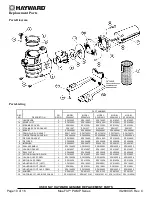


USE ONLY HAYWARD GENUINE REPLACEMENT PARTS
Page 3 of 16
Max-Flo™ PUMP Series
IS2800X5 Rev. C
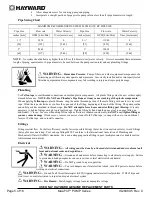
WARNING
– Hazardous Pressure.
Pool and spa water circulation systems operate under hazardous pressure during start up,
normal operation, and after pump shut off. Stand clear of circulation system equipment during pump start up. Failure to follow safety and
operation instructions could result in violent separation of the pump housing and cover, and/or filter housing and clamp due to pressure in
the system, which could cause property damage, severe personal injury, or death. Before servicing pool and spa water circulation system,
all system and pump controls must be in off position and filter manual air relief valve must be in open position. Before starting system
pump, all system valves must be set in a position to allow system water to return back to the pool. Do not change filter control valve
position while system pump is running. Before starting system pump, fully open filter manual air relief valve. Do not close filter manual
air relief valve until a steady stream of water (not air or air and water) is discharged.
WARNING
–
Separation Hazard.
Failure to follow safety and operation instructions could result in violent separation of
pump and/or filter components. Strainer cover must be properly secured to pump housing with strainer cover lock ring. Before servicing
pool and spa circulation system, filters manual air relief valve must be in open position. Do not operate pool and spa circulation system if a
system component is not assembled properly, damaged, or missing. Do not operate pool and spa circulation system unless filter manual air
relief valve body is in locked position in filter upper body.
WARNING
–
Risk of Electric Shock.
All electrical wiring MUST be in conformance with applicable local codes, regulations,
and the National Electric Code (NEC). Hazardous voltage can shock, burn, and cause death or serious property damage. To reduce the
risk of electric shock, do NOT use an extension cord to connect unit to electric supply. Provide a properly located electrical receptacle.
Before working on any electrical equipment, turn off power supply to the equipment.
WARNING
– To reduce the risk of electric shock replace damaged wiring immediately. Locate conduit to prevent abuse from
lawn mowers, hedge trimmers and other equipment.
WARNING
–
Electrical ground all electrical equipment before connecting to electrical power supply. Failure to ground all
electrical equipment can cause serious or fatal electrical shock hazard.
WARNING
–
Do NOT ground to a gas supply line.
WARNING
– To avoid dangerous or fatal electrical shock, turn OFF power to all electrical equipment before working on
electrical connections.
WARNING
– Failure to bond all electrical equipment to pool structure will increase risk for electrocution and could result in
injury or death. To reduce the risk of electric shock, see installation instructions and consult a professional electrician on how to bond all
electrical equipment. Also, contact a licensed electrician for information on local electrical codes for bonding requirements.
Notes to electrician:
Use a solid copper conductor, size 8 or larger. Run a continuous wire from external bonding lug to reinforcing rod
or mesh. Connect a No. 8 AWG (8.4 mm
2
) [No. 6 AWG (13.3 mm
2
) for Canada] solid copper bonding wire to the pressure wire connector
provided on the electrical equipment and to all metal parts of swimming pool, spa, or hot tub, and metal piping (except gas piping), and
conduit within 5 ft. (1.5 m) of inside walls of swimming pool, spa, or hot tub.
IMPORTANT
- Reference NEC codes for all wiring standards including, but not limited to, grounding, bonding and other general wiring
procedures.
WARNING
– Risk of Electric Shock. Connect only to a branch circuit protected by a ground-fault circuit-interrupter (GFCI).
Contact a qualified electrician if you cannot verify that the circuit is protected by a GFCI.
WARNING
– Risk of Electric Shock . The electrical equipment must be connected only to a supply circuit that is protected by a
ground-fault circuit-interrupter (GFCI). Such a GFCI should be provided by the installer and should be tested on a routine basis. To test
the GFCI, push the test button. The GFCI should interrupt power. Push reset button. Power should be restored. If the GFCI fails to
operate in this manner, the GFCI is defective. If the GFCI interrupts power to the electrical equipment without the test button being
pushed, a ground current is flowing, indicating the possibility of an electrical shock. Do not use this electrical equipment. Disconnect the
electrical equipment and have the problem corrected by a qualified service representative before using.
CAUTION –
This pump is intended for use with permanently-installed pools and may be used with hot tubs and spas if so
marked. Do not use with storable pools. A permanently-installed pool is constructed in or on the ground or in a building such that it
cannot be readily disassembled for storage. A storable pool is constructed so that it is capable of being readily disassembled for storage
and reassembled to its original integrity.
SAVE THESE INSTRUCTIONS


