background image


USE ONLY HAYWARD GENUINE REPLACEMENT PARTS


Page 4 of 16 

Max-Flo™ PUMP Series 

IS2800X5  Rev. C 

General Information 


Introduction 


This manual contains information for the proper installation and operation of the Hayward Max-Flo

 Series.  The 

instructions in this manual 

MUST

 be followed precisely.  

Failure to install according to defined instructions will void 

warranty. 


Product Benefits 


Exclusive swing-aside knobs make strainer cover removal easy.   


See-thru strainer cover lets you see when the basket needs cleaning. 


Strainer basket incorporates an integral an integral handle for easy removal.  Load extender ribbing ensures free flowing 
operations. 


Heavy-duty, high performance motor for quieter, cooler operation. 


Service-ease design gives simple access to all internal parts. 


Self-priming (suction lift up to 8’ above water level) 


Product Specifications 


Installation Instructions 
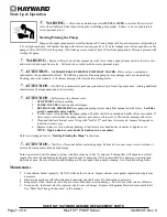


WARNING


This product should be installed and serviced only by a qualified professional.


Pump Location 


Locate pump as close to pool as practical and run suction lines as direct as possible to reduce friction 
loss.  Suction lines should have continuous slope upward from lowest point in line.  Joints must be tight 
(but not over-tightened).  Suction line diameter must equal or be larger than the discharge line diameter. 


Though the pump is designed for outdoor use, it is strongly advised to protect the electrical components 

from the weather.  Select a well-drained area, one that will not flood when it rains.  

Do NOT install pump in a damp or 

non-ventilated location.  

Keep motor clean.  Pump motors require free circulation of air for cooling.   


Pump Mounting 

 
Install pump on a firm, level base or pad to meet all local and national codes.  Fasten pump to base or pad with screws or 
bolts to further reduce vibration and stress on pipe or hose joints.  The base MUST be solid, level, rigid, and vibration free.  


Pump mount must: 


Allow pump inlet height to be as close to water level as possible. 


Allow use of short, direct suction pipe (to reduce friction losses). 


Allow for gate valves in suction and discharge piping. 


Be protected from excess moisture and flooding. 
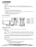
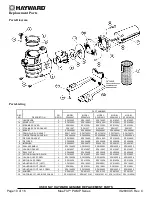
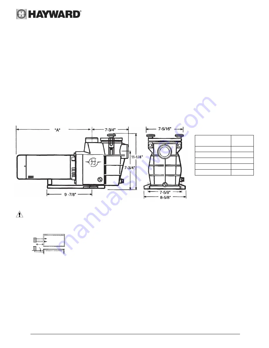
PUMP PART 

NUMBER 

LENGTH  

“A” 

SP2805X7 

14

"


SP2807X10 

14-3/8

"


SP2810X15 

15-1/2

"


SP2815X20 

16

"


SP2810X152 

13-7/8

"


Summary of Contents for Max-Flo SP2805X7

Page 1: ...in ground swimming pool spa that is equipped with large capacity filters heaters and pool cleaning equipment The Max Flo is a self priming pump that incorporates an improved seal and impeller design t...

Page 2: ...ely attached suction outlet components immediately o In addition two or more suction outlets per pump installed in accordance with latest ASME APSP Standards and CPSC guidelines follow all National St...

Page 3: ...uipment can cause serious or fatal electrical shock hazard WARNING Do NOT ground to a gas supply line WARNING To avoid dangerous or fatal electrical shock turn OFF power to all electrical equipment be...

Page 4: ...actical and run suction lines as direct as possible to reduce friction loss Suction lines should have continuous slope upward from lowest point in line Joints must be tight but not over tightened Suct...

Page 5: ...the fitting beginning at the end of the fitting The pump suction and outlet ports have molded in thread stops Do NOT attempt to force hose connector fitting past this stop It is only necessary to tig...

Page 6: ...und terminal to electrical service ground Bond motor to pool structure Bonding will connect all metal parts within and around the pool with a continuous wire Bonding reduces the risk of a current pass...

Page 7: ...pump and piping system using filter manual air relief valve See filter owner s manual for more details 4 If water source is higher than the pump pump will prime itself when suction and outlet valves...

Page 8: ...cover from strainer housing 3 Disconnect pump from mounting pad wiring system after power has been turned OFF and piping system 4 Once the pump is removed of water re install the strainer cover and d...

Page 9: ...t locations 8 Clean and lightly lubricate the impeller hub and seal recess in the seal plate with a dilute solution of non granulated liquid type soap 9 Gently wipe the black polished surface of the s...

Page 10: ...1 SPX1600R SPX1600R SPX1600R SPX1600R SPX1600R 8 DIFFUSER 1 SPX2800B SPX2800B SPX2800B SPX2800B SPX2800B 9 IMPELLER 1 SPX2605C SPX2607C SPX2610C SPX2615C SPX2610C 10 SEAL ASSEMBLY 1 SPX1600Z2 SPX1600Z...

Page 11: ...ring is clean Ensure o ring is properly seated in the cover o ring groove Ensure o ring is lubricated with Jack s 327 and that strainer cover is locked firmly in position Lubricant will help to creat...

Page 12: ...d suction line or leak at any joint low water level in pool and unrestricted discharge return lines Solution Correct suction condition or throttle return lines if practical Holding hand over return fi...

Page 13: ...r the nearest Hayward Authorized Service Center For assistance on your nearest Hayward Authorized Service Center please visit us at www haywardpool com Hayward shall not be responsible for cartage rem...

Page 14: ...USE ONLY HAYWARD GENUINE REPLACEMENT PARTS Page 14 of 16 Max Flo PUMP Series IS2800X5 Rev C THIS PAGE INTENTIONALLY LEFT BLANK...

Page 15: ...USE ONLY HAYWARD GENUINE REPLACEMENT PARTS Page 15 of 16 Max Flo PUMP Series IS2800X5 Rev C THIS PAGE INTENTIONALLY LEFT BLANK...

Page 16: ...tions Mail to Hayward Pool Products 620 Division Street Elizabeth NJ 07207 Attn Warranty Dept Or REGISTER YOUR WARRANTY ON LINE AT WWW HAYWARDNET COM DETACH HERE Fill out bottom portion completely and...

Reviews: