


USE ONLY HAYWARD GENUINE REPLACEMENT PARTS
Page 9 of 16
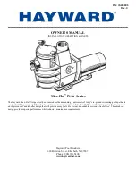
Max-Flo™ PUMP Series
IS2800X5 Rev. C
Removing the Impeller
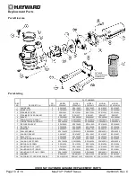
(See Parts Diagram on page 10 of this manual for pump component locations.)
3.
Remove the motor end cover by removing the two (2) screws or pry off the cap covering the motor shaft. Hex
shaped caps must be twisted off.
4.
To prevent motor shaft from turning, carefully slide a 7/16" open-end wrench between the capacitor and the
centrifugal switch (the wrench fits over the two (2) flats on the motor shaft). Some motors may require a larger
wrench be placed in slot at end of shaft to keep motor shaft from turning.
5.
Rotate the
impeller
counterclockwise and remove. The spring portion of the
seal assembly
is now exposed.
Note carefully the position of the spring seal, and remove it.
NOTE -
Replace motor cover to protect delicate
motor parts.
Removing the Ceramic Seat
(See Parts Diagram on page 10 of this manual for pump component locations.)
6.
Remove the
seal plate
. Note the tabs on the sides of the plate and the mating grooves on the front of the
motor
mounting plate
.
7.
Press the ceramic seat with rubber cup out of the
seal plate
. If tight, use a small screwdriver to tap seal out.
STOP
- Clean all recesses & parts to be reassembled. Inspect gaskets & replace if necessary.
Seal Installation
(See Parts Diagram on page 10 of this manual for pump component locations.)
8.
Clean and lightly lubricate the impeller hub and seal recess in the seal plate with a dilute solution of non-
granulated liquid-type soap.
9.
Gently wipe the black, polished surface of the spring seal assembly with a clean, soft, cotton cloth. Press the
spring seal assembly onto the
impeller
hub – black polished surface facing away from the impeller.
10.
Gently wipe the polished surface of the ceramic seal with a clean, soft, cotton cloth. Lubricate the rubber cup
on the ceramic seat and press it firmly and evenly into the recess of the
seal plate
– polished side facing out.
Replacing the Impeller and Diffuser
(See Parts Diagram on page 10 of this manual for pump component locations.)
11.
Place the
seal plate
onto the
motor mounting plate
, aligning the tabs on the
seal plate
with the grooves on the
motor mounting plate
.
12.
Screw the
impeller
onto the motor shaft in a clockwise direction. Tighten snugly by holding motor shaft with
wrench as noted in step #4.
13.
Place the
diffuser
over the
impeller
onto the
seal plate
fitting positioning lug between the two (2) guides.
Replacing the Motor Assembly
(See Parts Diagram on page 10 of this manual for pump component locations.)
14.
Fasten motor end cover by using the two (2) hex shaped screws. Slide the motor assembly with the
diffuser
in
place, into
pump/strainer housing
, being careful not to disturb the
diffuser gasket
.
15.
Fasten assembly to
pump/strainer housing
using the four (4) 3/8”" x 2"
housing cap screws
. (Be sure
housing gasket
is in place, and replace if damaged). Tighten alternately and evenly.