
USE ONLY HAYWARD GENUINE REPLACEMENT PARTS
Page 13 of 24
Max-Flo VS Pump
IS2300VSP Rev C
1.
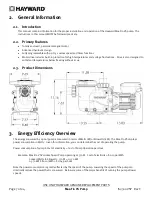
Preset Speeds:
Buttons labeled V1 thru V3 can be used to run the pump at a predetermined speed for a certain
length of time. Preset Speed settings can be quickly updated using the
▲
and
▼
arrow buttons to change the
speed and then pressing both
▲
and
▼
arrow buttons simultaneously to save the new speed setting. When a
speed is selected, the LED beside the button will illuminate to indicate operation.
a.
Start UP
This pump is set to start in prime mode. When Priming has finished the pump will then switch to speed V3.
The pump will run at this speed for its programmed time then switch to speed V1. The pump will then
remain at speed V1 until power is cycled or another speed is selected.
b.
Default Speeds / TIME:
V1: 1500 rpm
V2: 2400 rpm / 12 hours
V 3: 3000 rpm / 12 hours
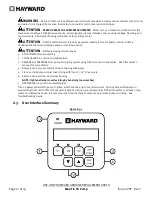
2.
Menu/navigation buttons:
The DISP/FUNC button will scroll through the home screen information when
pressed. If the DISP/FUNC button is held for several seconds it will enter the controller into configuration mode.
The
▲
and
▼
arrow buttons are used to change parameters within configuration mode.
3.
Power LED:
The POWER LED will remain illuminated while the unit has power unless the pump is experiencing an
error. When the pump experiences an error the POWER LED will FLASH.
4.
Run/Stop:
This button is used to stop the pump to allow strainer basket cleaning, etc. When this button is
pressed, the pump will remain stopped until the button is pressed a second time to resume normal operation.
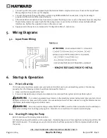
6.4.
Menu Outline
1.
Configuration Menu
(see section 6.6 for basic product configuration)
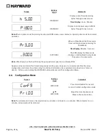
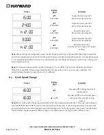
a.
Prime Mode Speed
b.
V1 Speed
c.
V2 Speed
d.
V2 Timer
e.
V3 Speed
f.
V3 Timer
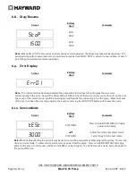
6.5.
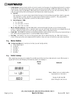
Initial startup
After plumbing and wiring are complete, the variable speed drive must be configured prior to use. When power is
applied to the drive, the following informational screens are displayed.
Screen
Buttons
Used
Comments
.
Pump software revision number will be
displayed across the screen.
DISP/FUNC
Displays the Motor RPM
Cycles through to next screen