USE ONLY HAYWARD GENUINE REPLACEMENT PARTS
Page 19 of 24
Max-Flo VS Pump
IS2300VSP Rev C
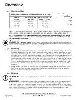
9.6.
Replacing the Motor Assembly
13.
Slide the motor assembly, with the diffuser in place, into pump/strainer housing, being careful not to disturb the
diffuser gasket.
14.
Fasten assembly to pump/strainer housing using the four (4) 5/16" x 1.75" bolts. (Be sure housing gasket is in
place, and lubricated. Replace if damaged). Tighten bolts alternately and evenly to 185 inch-pounds. Looking at
the back of the pump, start with the top right, move diagonal to the bottom left, then up to the top left and last
across to the bottom right.
10.
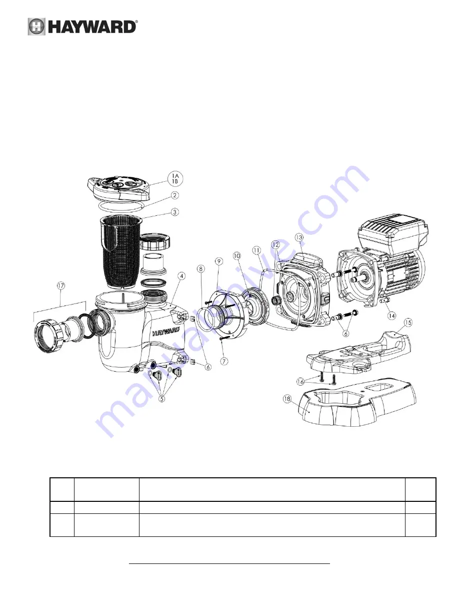
Replacement Parts
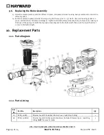
10.1.
Parts Diagram
10.2.
Parts Listing
Ref.
No.
Part No.
Description
Qty.
1A
SPX2300DLS
Strainer Cover Kit (Includes Strainer Cover, Lock-Ring, O-Ring)
1
1B
SPX2300DLSB
Strainer Cover Kit for Biguanide Sanitizers (Includes Strainer Cover, Lock-Ring,
O-Ring)
NOT
Pressure Testable
1


