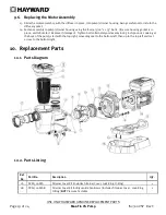
USE ONLY HAYWARD GENUINE REPLACEMENT PARTS
Page 6 of 24
Max-Flo VS Pump
IS2300VSP Rev C
WARNING
– To Reduce the risk of Entrapment Hazards:
When outlets are small enough to be blocked by a person, a minimum of two functioning suction outlets per
pump must be installed. Suction outlets in the same plane (i.e. floor or wall), must be installed a minimum of
three feet (3’) [0.91 meter] apart, as measured from near point to near point.
Dual suction fittings shall be placed in such locations and distances to avoid “dual blockage” by a user.
Dual suction fittings shall not be located on seating areas or on the backrest for such seating areas.
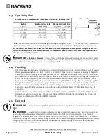
The maximum system flow rate shall not exceed the values shown in the “Pipe Sizing Chart” found in section
4.3 below.
Never use pool or spa if any suction outlet component is damaged, broken, cracked, missing, or not securely
attached.
Replace damaged, broken, cracked, missing, or not securely attached suction outlet components
immediately.
In addition to two or more suction outlets per pump installed in accordance with latest APSP standards and
CPSC guidelines, follow all national, state, and local codes applicable.
Installation of a vacuum release or vent system, which relieves entrapping suction, is recommended.
WARNING
– Hazardous Pressure
.
Pool and spa water circulation systems operate under hazardous
pressure during start-up, normal operation, and after pump shut-off. Stand clear of circulation system equipment
during pump start-up. Failure to follow safety and operation instructions could result in violent separation of the
pump housing and cover due to pressure in the system, which could cause property damage, severe personal injury,
or death. Before servicing pool and spa water circulation system, all system and pump controls must be in off
position and filter manual air relief valve must be in open position. Before starting pump, all system valves must be
set in a position to allow system water to return back to the pool. Do not change filter control valve position while
pump is running. Before starting pump, fully open filter manual air relief valve. Do not close filter manual air relief
valve until a steady stream of water (not air or air and water mix) is discharged from the valve. All suction and
discharge valves MUST be OPEN when starting the circulation system. Failure to do so could result in severe
personal injury and/or property damage.
WARNING
– Separation Hazard
.
Failure to follow safety and operation instructions could result in violent
separation of pump components. Strainer cover must be properly secured to pump housing with strainer cover lock
ring. Before servicing pool and spa circulation system, all system and pump controls must be in off position and
filter manual air relief valve must be in open position. Do not operate pool and spa circulation system if a system
component is not assembled properly, damaged, or missing. Do not operate pool and spa circulation system unless
filter manual air relief valve body is in locked position in filter upper body. All suction and discharge valves MUST be
OPEN when starting the circulation system. Failure to do so could result in severe personal injury and/or property
damage.
WARNING
– Never operate the circulation system at more than 50 PSI maximum.
WARNING
– Fire and burn hazard
.
Motors operate at high temperatures and if they are not properly isolated
from any flammable structures or foreign debris they can cause fires, which may cause severe personal injury or
death. It is also necessary to allow the motor to cool for at least 20 minutes prior to maintenance to minimize the
risk for burns.
WARNING
– Failure to install according to defined instructions may result in severe personal injury or death.
SAVE THESE INSTRUCTIONS