
USE ONLY HAYWARD GENUINE REPLACEMENT PARTS
Page 8 of 24
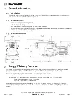
Max-Flo VS Pump
IS2300VSP Rev C
Benefits of running at low speeds
Save electricity and money
Improved filtration – the filter can often remove smaller particles when the water moves slower
Quiet operation
Reduced Total Dynamic Head – less stress on equipment (e.g. filter) which can lengthen equipment life
When determining the speed(s) to operate your pump, you must also take into account the minimum requirements for
proper sanitation and equipment/water feature functionality.
It is recommended you filter (“turnover”) all the water in the pool at least once every 24 hours. Check with local
requirements for the minimum turnover rate. Running the pump at a lower speed may require running the pump for a
longer period of time in order to meet the turnover requirements for proper sanitation.
Equipment such as heaters, skimmers, and chlorinators require minimum flows to operate correctly. Refer to individual
equipment manuals for specific flow requirements.
After setting the pump speed(s), it is recommended you check that all other equipment/water features are functioning as
intended. For example, when running at a low speed for daily filtration, verify water is adequately flowing over the
skimmer weirs. Operate the pump at higher speeds for the shorter periods of time needed to operate a heater, water
feature, etc.
4.
Installation and Wiring
WARNING
– This product should be installed and serviced only by a qualified professional.
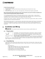
4.1.
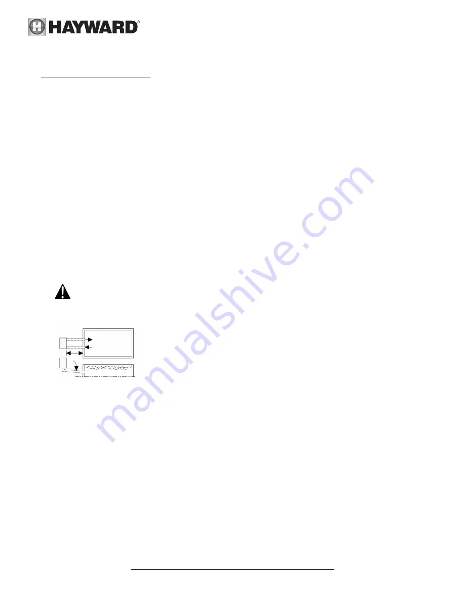
Pump Location
Locate pump as close to pool as practical and run suction lines as direct as possible to
reduce friction loss. Suction lines should have continuous slope upward from lowest
point in line. Joints must be tight (but not over-tightened). Suction line diameter must
equal or be larger than the discharge line diameter.
Though the pump is designed for outdoor use, it is advised to place pump and filter in the
shade to shield them from continuous direct heat. Select a well-drained area that will not
flood when it rains. Do NOT install pump and filter in a damp or non-ventilated location. Keep motor clean. Pump
motors require free circulation of air for cooling.
4.2.
Pump Mounting
Install pump on a level concrete slab or other rigid base to meet all local and national codes. Secure pump to base
with screws or bolts to further reduce vibration and stress on pipe or hose joints. The base must be level, rigid, and
vibration free.
Pump mount must:
Allow pump inlet height to be as close to water level as possible.
Allow use of short, direct suction pipe (to reduce friction losses).
Allow for valves in suction and discharge piping.
Be protected from excess moisture and flooding.
Allow adequate access for servicing pump and piping.


