
USE ONLY HAYWARD GENUINE REPLACEMENT PARTS
Page 9 of 24
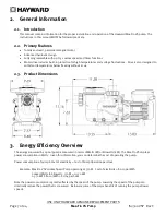
Max-Flo VS Pump
IS2300VSP Rev C
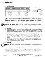
4.3.
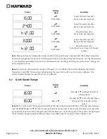
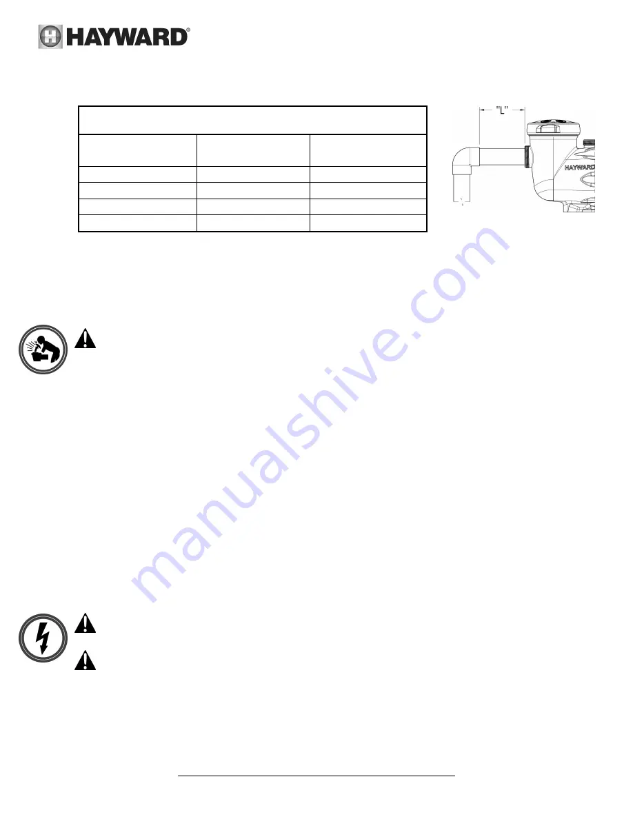
Pipe Sizing Chart
MAXIMUM RECOMMENDED SYSTEM FLOW RATE BY PIPE SIZE
Pipe Size
in. [mm]
Maximum Flow Rate
GPM [LPM]
Minimum Straight Pipe
Length “L” in. [mm] *
1 ½” [50]
45 [170]
7 ½” [190]
2” [63]
80 [300]
10” [254]
2 ½” [75]
110 [415]
12 ½” [317]
3” [90]
160 [600]
15” [381]
* Note:
It is recommended that a minimum length of straight piping (shown as “L” in above diagram), equivalent to
5 pipe size diameters, be used between the pump suction inlet and any plumbing fittings (elbows, valves, etc.).
When installing the Max-Flo VS, care should be taken to ensure proper pipe and equipment sizing to handle the
maximum flow required. It is recommended to set the maximum speed in order to not exceed the maximum flow
rate. See note at end of section 6.6.
WARNING
– Hazardous Pressure
. Pumps, filters, and other equipment/ components of a swimming pool
filtration system operate under pressure. Incorrectly installed and/or improperly tested filtration equipment and/or
components may fail resulting in severe personal injury or death.
4.4.
Plumbing
1.
Use Teflon tape to seal threaded connections on molded plastic components. All plastic fittings must be new or
thoroughly cleaned before use. NOTE - Do NOT use Plumber’s Pipe Dope as it may cause cracking of the plastic
components. When applying Teflon tape to plastic threads, wrap the entire threaded portion of the male fitting
with one to two layers of tape. Wind the tape clockwise as you face the open end of the fitting, beginning at the
end of the fitting. The pump suction and outlet ports have molded-in thread stops. Do NOT attempt to force
hose connector fitting past this stop. It is only necessary to tighten fittings enough to prevent leakage. Tighten
fitting by hand and then use a tool to engage fitting an additional 1 ½ turns. Use care when using Teflon tape as
friction is reduced considerably; do NOT over-tighten fitting or you may cause damage. If leaks occur, remove
connector, clean off old Teflon tape, re-wrap with one to two additional layers of Teflon tape, and re-install
connector.
2.
Fittings (elbows, tees, valves, etc.) restrict flow. For better efficiency, use the fewest possible fittings. Avoid
fittings that could cause an air trap. Pool and spa fittings MUST conform to the International Association of
Plumbing and Mechanical Officials (IAPMO) standards.
4.5.
Electrical
WARNING
– All electrical wiring MUST conform to local codes, regulations, and the National Electric Code
(NEC).
WARNING
– Ground and bond pump before connecting to electrical power supply. Failure to ground and
bond pump can cause serious or fatal electrical shock hazard. Do NOT ground to a gas supply line. To avoid
dangerous or fatal electrical shock, turn OFF power to pump before working on electrical connections. Fire Hazard -
match supply voltage to pump nameplate voltage. Insure that the electrical supply available agrees with the pump’s
voltage, phase, and cycle, and that the wire size is adequate for the amps rating and distance from the power
source. Use copper conductors only.


