www.haywardpool.com USE ONLY HAYWARD GENUINE REPLACEMENT PARTS
Max-Flo II
™
Series _____ _____ _____ _____ ___________________Page 3 of 16
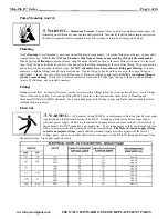
WARNING
–
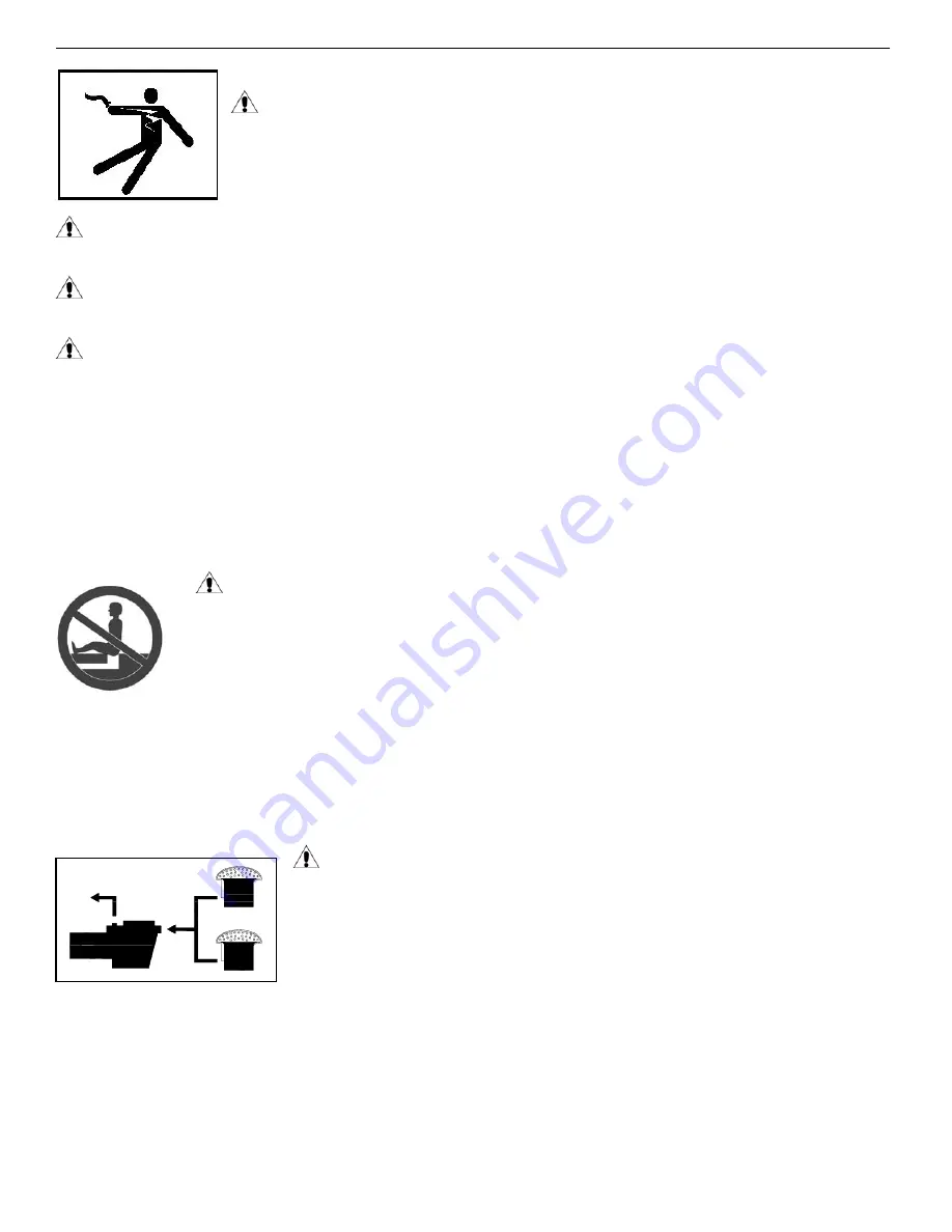
Risk of Electric Shock.
All electrical wiring MUST be in conformance with all
applicable local codes, regulations, and the National Electric Code (NEC). Hazardous voltage can shock,
burn, and cause death or serious property damage. To reduce the risk of electric shock, do NOT use an
extension cord to connect unit to electric supply. Provide a properly located electrical receptacle. Before
working on pump or motor, turn off power supply to the pump.
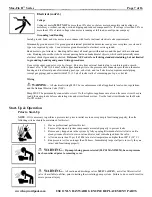
WARNING
–
To reduce the risk of electric shock replace damaged wiring immediately. Locate conduit to prevent abuse
from lawn mowers, hedge trimmers and other equipment.
WARNING
–
It is recommended to install a Ground Fault Circuit Interrupter (GFCI) in the circuit, however, all
electrical wiring MUST be in conformance with all applicable local codes, regulations, and the National Electric Code (NEC).
WARNING
–
Failure to bond pump to pool structure will increase risk for electrocution and could result in injury or
death. To reduce the risk of electric shock, see installation instructions and consult a professional electrician on how to bond pump.
Also, contact a licensed electrician for information on local electrical codes for bonding requirements.
Notes to the electrician
:
Use a solid copper conductor, size 8 or larger. Run a continuous wire from external bonding lug to reinforcing rod or mesh. Connect
a No. 8 AWG (8.4 mm
2
) solid copper bonding wire to the pressure wire connector provided on the motor housing and to all metal
parts of swimming pool, spa, or hot tub, and to all electrical equipment, metal piping (except gas piping), and conduit within 5 ft. (1.5
m) of inside walls of swimming pool, spa, or hot tub.
IMPORTANT
- Reference NEC codes for all wiring standards including, but
not limited to, grounding, bonding and other general wiring procedures.
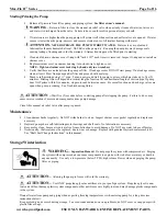
WARNING
–
Suction Entrapment Hazard.
Suction in suction outlets and/or suction outlet covers, which are damaged, broken, cracked, missing, or
unsecured cause severe injury and/or death due to the following entrapment hazards:
Hair Entrapment
- Hair can become entangled in suction outlet cover.
Limb Entrapment
- A limb inserted into an opening of a suction outlet sump or suction outlet cover that is
damaged, broken, cracked, missing, or not securely attached can result in a mechanical bind or swelling of the
limb.
Body Suction Entrapment
- A pressure applied to a large portion of the body or limbs can result in an entrapment.
Evisceration/ Disembowelment
- A negative pressure applied directly to the intestines through an unprotected suction outlet
sump or suction outlet cover which is damaged, broken, cracked, missing, or unsecured can result in
evisceration/disembowelment.
Mechanical Entrapment
- There is potential for jewelry, swimsuits, hair decorations, fingers, toes, or knuckles to be caught
in an opening of a suction outlet cover resulting in mechanical entrapment.
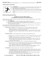
WARNING
-
To Reduce the risk of Entrapment Hazards:
- When outlets are small enough to be blocked by a person, a minimum of two functioning
suction outlets per pump must be installed. Suction outlets in the same plane (i.e. floor or wall),
must be installed a minimum of three feet (3’) [0.91 meter] apart, as measured from near point
to near point.
- Dual suction fittings shall be placed in such locations and distances to avoid “dual blockage”
by a user.
- Dual suction fittings shall not be located on seating areas or on the backrest for such seating
areas.
- The maximum system flow rate shall not exceed the values shown in the “Pipe Sizing Chart” found at the bottom of page 5
of this manual.
- Never use pool or spa if any suction outlet component is damaged, broken, cracked, missing, or not securely attached.
- Replace damaged, broken, cracked, missing, or not securely attached suction outlet components immediately.
- In addition to two or more suction outlets per pump installed in accordance with latest IAF (formerly NSPI) standards and
CPSC guidelines, follow all national, state, and local codes applicable.
- Installation of a vacuum release or vent system, which relieves entrapping suction, is recommended.


