
www.haywardpool.com USE ONLY HAYWARD GENUINE REPLACEMENT PARTS
Max-Flo II
™
Pump Series __________
_____ ________________________ Page 4 of 16
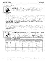
WARNING
–
Hazardous Pressure.
Pool and spa water circulation systems operate under
hazardous pressure during start-up, normal operation, and after pump shut-off. Stand clear of circulation
system equipment during pump start-up. Failure to follow safety and operation instructions could result in
violent separation of the pump housing and cover due to pressure in the system, which could cause property
damage, severe personal injury, or death. Before servicing pool and spa water circulation system, all
system and pump controls must be in off position and filter manual air relief valve must be in open
position. Before starting system pump, all system valves must be set in a position to allow system water to
return back to the pool. Do not change filter control valve position while system pump is running. Before
starting system pump, fully open filter manual air relief valve. Do not close filter manual air relief valve until a steady stream of water
(not air or air and water) is discharged. All suction and discharge valves
MUST
be
OPEN
when starting the circulation system.
Failure to do so could result in severe personal injury and/or property damage.
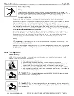
WARNING
–
Separation Hazard.
Failure to follow safety and operation instructions could
result in violent separation of pump components. Strainer cover must be properly secured to pump housing
with strainer cover lock ring. Before servicing pool and spa circulation system, all system and pump
controls must be in off position and filter manual air relief valve must be in open position. Do not operate
pool and spa circulation system if a system component is not assembled properly, damaged, or missing. Do
not operate pool and spa circulation system unless filter air relief valve body is in locked position in filter
upper body. All suction and discharge valves
MUST
be
OPEN
when starting the circulation system.
Failure to do so could result in severe personal injury and/or property damage.
WARNING
–
Never operate or test the circulation system at more than 50 psi.
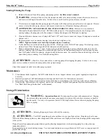
WARNING
–
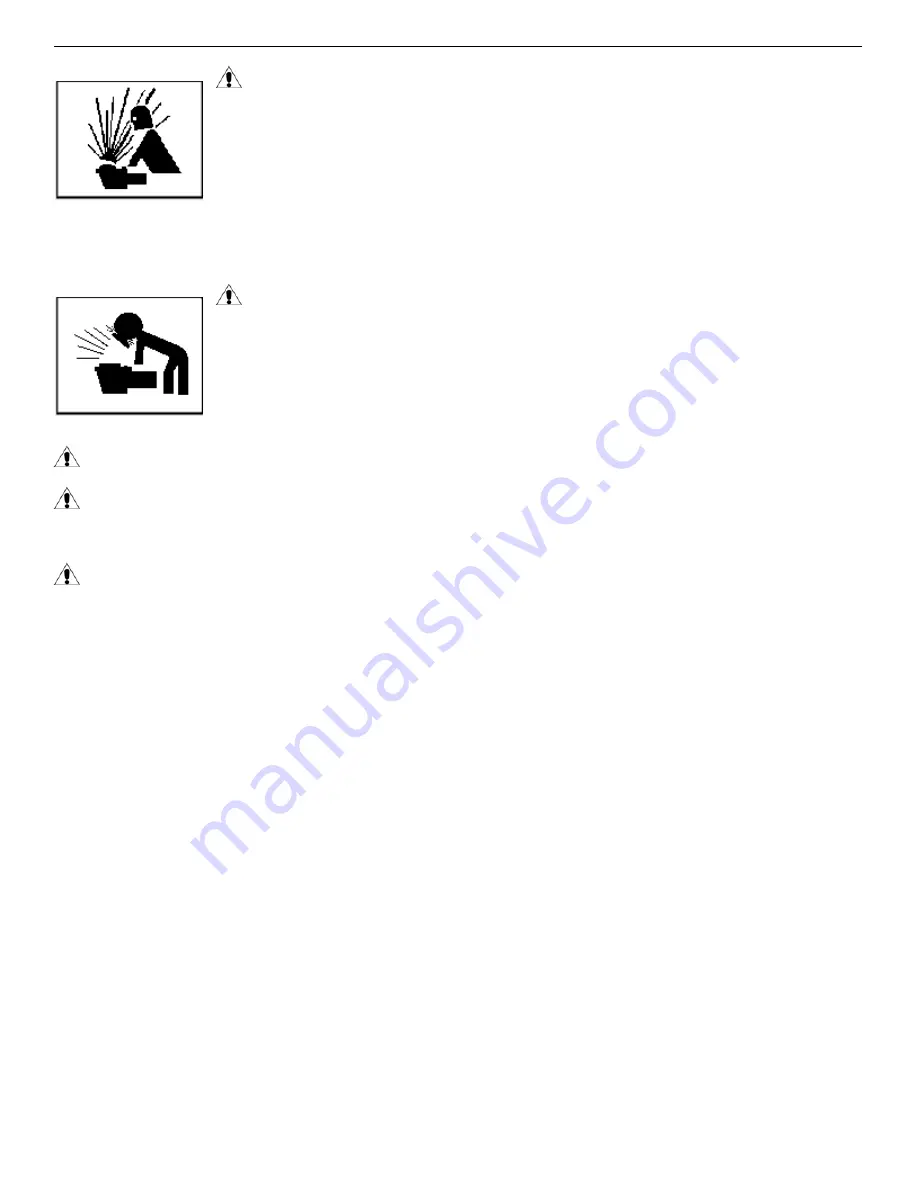
Fire and burn hazard.
Motors operate at high temperatures and if they are not properly isolated from
any flammable structures or foreign debris they can cause fires, which may cause severe personal injury or death. It is also necessary
to allow the motor to cool for at least 20 minutes prior to maintenance to minimize the risk for burns.
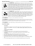
WARNING
–
Failure to
install according to all defined instructions may result in severe personal injury or death.
General Information
Introduction
This manual contains information for the proper installation and operation of the Hayward Max-Flo II
TM
Series. The
instructions in this manual
MUST
be followed precisely.
Failure to install according to defined instructions will void
warranty.
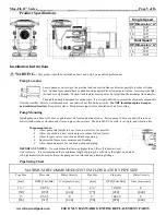
Product Features & Benefits
•
Self-priming.
•
Tri-Lock cam and ramp strainer cover are designed to seal with less than quarter turn.
•
Clear strainer cover lets you see when the basket needs cleaning. Pressure testable to 50 psi
MAXIMUM.
•
Large leaf holding capacity strainer basket extends time between cleanings.
•
Heavy-duty, high performance motor is designed to operate in environments up to 122° F.
•
Elevated base insures better air circulation for cooler running and prevents flooding.
•
All components molded of corrosion-proof reinforced engineered plastic for extra durability and long
life.
•
Service-Ease Design provides easy access to all internal components by just removing 4 bolts.


