VSC Pump Address Setting
The VSC address must be set to 001 when using the VSC with the OnCommand. Refer to the TriStar Pump
Owner’s Manual (IS3220VSC) and Hayward document IS3220VSCAQLL for specific instructions on setting
the pump address.
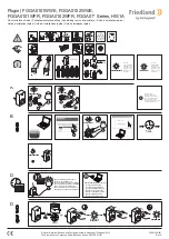
Temperature Sensors
The OnCommand utilizes 10K ohm thermistor type sensors. Three sensors (water temperature, air temperature
and solar temperature) are included. If the OnCommand is being used to control a solar heating system, the solar
sensor is required. The sensors are provided with a 15 ft. cable. If a longer cable is required, contact the Goldline
Technical Support department for information on suitable cable types and splices.
See page 2 and the diagram
below for installation information.
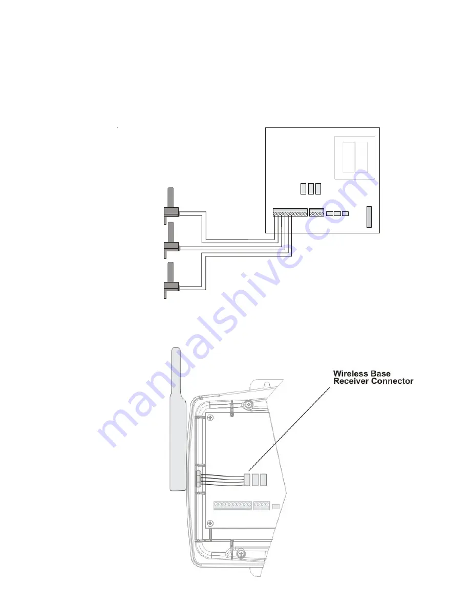
Base Station
Plug in the pigtail connector from the wireless base station into the “wireless” connector on the main PCB in the
OnCommand control unit.
12
Variable Speed in Groups
The OnCommand can be programmed to use alternate pump speeds while running a group command. This allows
the pump to be set to a higher or lower speed than normal, while the group is activated. When the group stops, the
speed will return to its normal setting.
Changing the speed setting while the group is running will make the group release the alternate speed setting and
revert back to the normal speed setting. Any changes that are made at that point will affect the normal speed
setting. The next time the group is activated, the speed will return to the group speed setting that was originally
programmed in the Configuration Menu. To change the speed setting while the group is running, go to the Settings
menu and press the +/- button while “Group Control” is displayed. The speed setting will change to the normal
speed setting.
Accessing the Configuration Menus
Configuring the OnCommand requires that you navigate through the Configuration Menu and input various infor-
mation. For more detailed information about using the OnCommand menu system, refer to the Operation Manual.
To access the Configuration Menu
Configuration
Menu-Unlocked
Configuration
Menu-Locked
Press repeatedly until “Configuration Menu” is displayed
Move to configuration menu items
Press BOTH buttons SIMULTANEOUSLY for 5 seconds to unlock
NOTE: The configuration menu automatically “locks” after 2 minutes of no buttons being pressed to
prevent unauthorized people from changing the control logic inadvertently and possibly damaging
the pool equipment or causing a “call back” to fix the configuration.
Configuration Menu Items
Each item needs to be programmed and may contain additional sub-menu items. Refer to the following pages for
information on programming.
Move to next menu item
Ext. Chlorinator
Enabled
Display
Salt
Chlor. Config.
+ to view/change
Toggle between Display Salt (default) and Minerals
Toggle between External Chlorinator Enabled and Disabled (default)
Move to previous/next configuration menu
Move to next configuration menu
Push to access Chlorinator option
Chlorinator
If the optional external chlorinator is enabled (requires the use of a Goldline Aqua Rite or Hayward
Swimpure chlorinator), the OnCommand will automatically chlorinate both the pool and spa according
to the desired output setting (see Settings Menu in the Operation manual). If disabled (default), all
displays relating to the chlorinator will be suppressed.
When the chlorinator is enabled, the OnCommand will automatically detect and control any Aqua
Rite/Swimpure(s) that is installed in the system.
Display
Allows for the display of salt (default) or mineral values.
15
AIR
SENSOR
SOLAR
SENSOR
POOL/SPA
SENSOR
optional