3. Electrical Wiring
•
Ensure that Power is disconnected prior to wiring the OnCommand
•
Follow all local and NEC (CEC if applicable) codes
•
Use copper conductors only
The OnCommand requires both high and low voltage connections. To gain access to the wiring compartments,
open the door and remove the left and right panel covers. A divider separates the OnCommand into low voltage
and high voltage compartments. All low voltage connections will be made to the printed circuit board (PCB) on the
left side of the divider. These connections include actuators, sensors, heaters, etc. All high voltage connections
such as PCB input power, pumps, lights, etc. are made on the right side of the divider.
Grounding
A ground bus bar is located in the high voltage compartment of the OnCommand. Connect a ground wire from the
primary electrical panel to this ground bus bar. Also use this ground bar to ground each piece of high voltage (120
or 240VAC) equipment that is connected to the OnCommand control relays.
High Voltage Wiring
Input Wiring
The OnCommand requires 120VAC, .6A input power to operate the control logic circuits under maximum load.
This power should come from a circuit breaker rated at 125% of the intended load or the next higher size available.
Leads are supplied for input wiring as shown on the diagram on the following page.
5
22
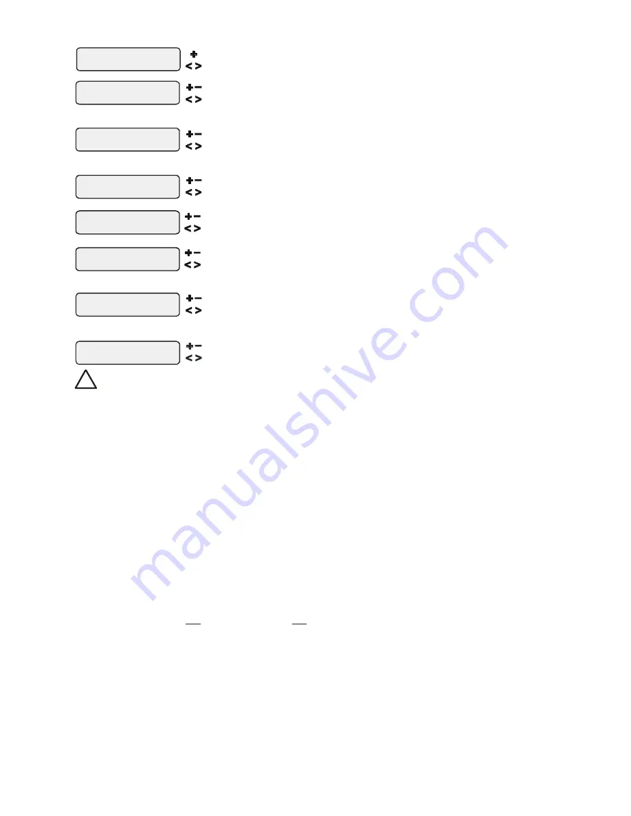
NOTE: The configuration parameters for the Aux2 output are the same as shown below for Aux1.
Aux1 Pump Spd
Settings Menu
Select between Settings Menu (default) and the desired pump speed
only if filter pump is set to variable
and relay type is set to standard
Move to previous/next configuration menu
Aux1 Config.
+ to view/change
Aux1 Function
Manual On/Off
Aux1 Relay
Standard
Push to access Aux options
Toggle between Standard (default) and Dimmer
Move to previous/next configuration menu
Move to next menu item or previous/next configuration menu
Aux1 Interlock
Disable
Aux1 Freeze
Disable
Toggle between Enabled and Disabled (default) Aux1 Interlock
T
oggle between Enabled
and Disabled Aux1 Freeze
(default)
Move to next menu item
Move to previous/next configuration menu
for manual on/off, countdown
timer and timeclock functions
Move to next menu item
Rotates between
Manual On/Off (default), Countdown Timer,
Low Speed- Filter, Timeclock, Solar, and Super Chlorinate
for all functions except dimmer relay, solar
super chlorinate, and low speed
f
super chlorinate, and low speed
or all functions except dimmer relay,
Aux1 Group
Filter: Unaffected
Aux1 Group
Timer: None(Manual)
Options available depend on the function that is selected
Rotates between Manual On/Off (default),Countdown Timer and Timeclock
Move to previous/next menu item or next configuration menu
Move to next menu item
for group function only
for group function only
!
WARNING: Do not use the OnCommand to control an automatic pool cover. Swim-
mers may become entrapped underneath the cover.
Aux1 Function
Manual On/Off (default)
—the aux relay will alternate between turning on and off when the aux button
is pressed. There is no automatic control logic.
Countdown Timer
– the aux relay will turn on when the AUX button is pressed and then will turn off
automatically after a programmed time (see Timers Menu, Operation Manual). The AUX button can
also be used to turn the output off.
Low Speed of a 2-speed Filter Pump
– the OnCommand will operate the aux relay whenever the low
speed operation of the filter pump is required. It is very important that the “2-speed” filter pump
option be selected under the “Filter Config.” Menu for proper operation.
Timeclock
– the aux relay will turn-on and turn-off at the times set for the aux1 timeclock in the Timers
Menu. The AUX button can also be used to turn the output on and off.
Solar
– the aux relay operates a solar booster pump which will turn on when the filter pump is running
and solar heat is available and the water is less than the desired temperature setting. It is important to
note that “Solar Control” must be enabled in the “Solar Config.” menu for proper operation to occur.
Group
– the aux relay operates when the Group function is initiated and shuts off when the Group
function is terminated. See Aux1 Group section for operation information for the Group function.
Super Chlorinate
– if “Chlorinator” is enabled, this option allows the user to start a Super Chlorinate
cycle when the Aux button is pressed, rather than using the Settings Menu. Note that only one
button can be assigned to this function.


