3
Base Station
The AQL2-BASE-RF base station must be installed if the AQL2-SS-RF or AQL2-POD will be used. To install
the base station, remove the knockout on the upper left side of the OnCommand main control unit, insert the base
station, and then tighten the nut from the inside. Also refer to the Base Station installation manual and the diagram
on page 12.
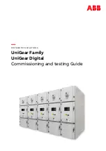
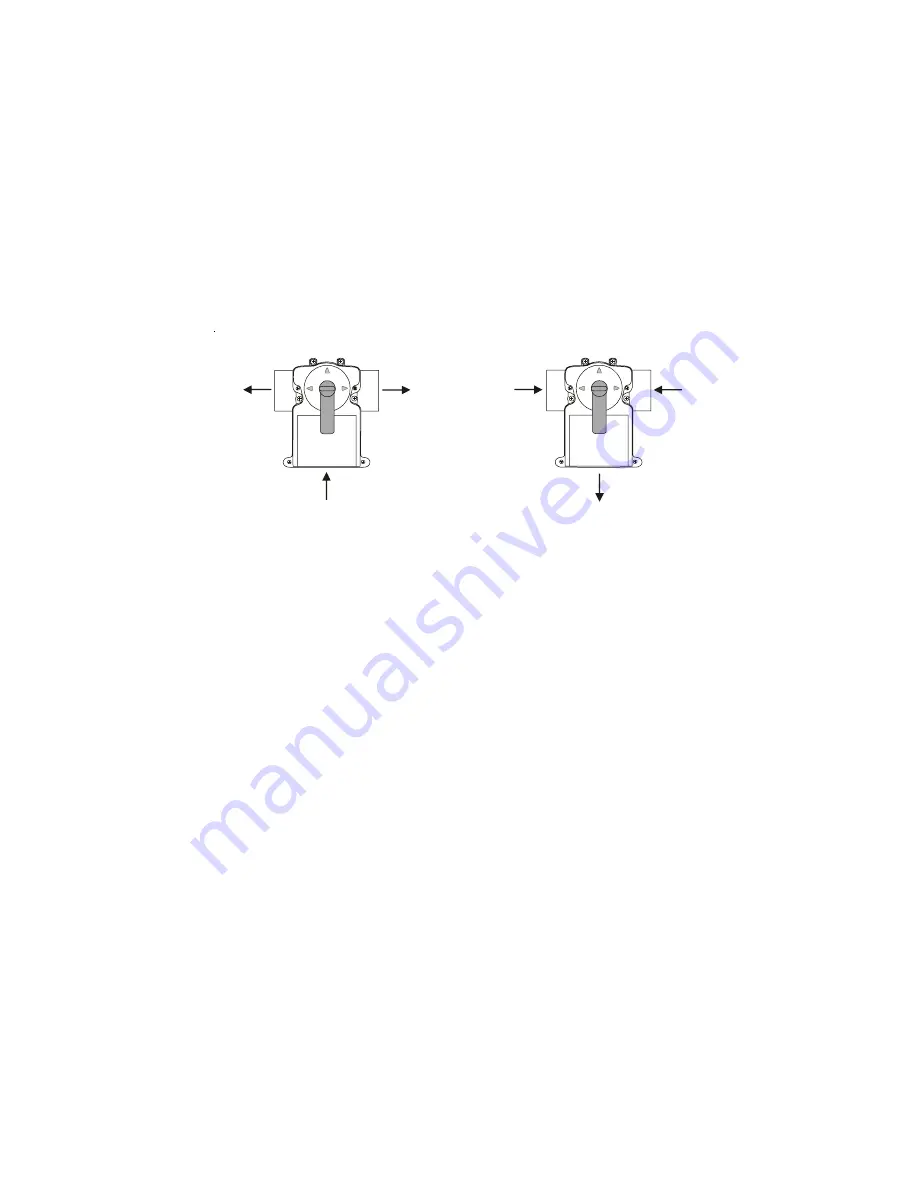
Optional Valve Actuators
(included with ONCOM-ACT, ONCOM-ACT-RC)
For optional actuators used with the OnCommand—note that the internal cams in the actuator may also have to be
adjusted depending on the way the actuator is mounted on the valve and the desired valve action.
RETURN
SUCTION
OUT
(Common)
IN
(Common)
OUT
IN
OUT
IN
24
Valve3 Pump Spd
Settings Menu
Select between Settings Menu (default) and the desired pump speed
only if filter pump is set to variable
and relay type is set to standard
Move to previous/next configuration menu
Valve3 Freeze
Disabled
Toggle between Enabled and Disabled (default) Valve3 Freeze
Move to previous/next configuration menu
for all functions except super chlorinate
Valve3 Config.
+ to view/change
Valve3 Function
Solar
Push to access Valve3 options
Rotates between
k
Timecloc (default), Solar, In-floor Cleaner,
Filter, Lights, Aux1 and Aux2
Move to previous/next configuration menu
Move to next menu item
Valve3 Interlock
Disabled
Toggle between Enabled and Disabled (default) Valve3 Interlock
Move to next menu item
for all functions except solar and super chlorinate
Valve3 Function
Timeclock (default)
– the valve turns on/off at the times set for the valve3 timeclock in the Timers
Menu (see Operations Manual).
Solar
– the valve operates when the filter pump is running and solar heat is available and the water is
less than the desired temperature setting. Solar heating must be enabled in the “Solar Config. menu
for proper operation to occur.
In-Floor Cleaner
– the valve switches the water returning to the pool between the in-floor cleaner and
the normal return jets which facilitate efficient surface skimming. The valve will operate the in-floor
cleaner for the first half of each clock hour and then switch to the jets/skimming for the last half of the
hour.
Group
– the valve operates when the Group function is initiated and shuts off when the Group
function is terminated. See Valve3 Group section for operation information for the Group function.
Valve3=Filter
– the valve operates whenever the Filter relay is on.
Valve3=Lights
– the valve operates whenever the Lights relay is on.
Valve3=Aux1
– the valve operates whenever the Aux1 relay is on.
Valve3=Aux2
– the valve operates whenever the Aux2 relay is on.
Valve3 Interlock
If “Enabled”, this feature will override the function (timeclock or in-floor cleaner) selected above and
turn the valve off when: the filter pump is off, first 3 minutes of filter pump operation (allows the pump
to prime and get water flowing), or for the first 3 minutes after solar turns on (allows air in the solar
panels to be purged). Interlock is not available for solar or super chlorinate.
Valve3 Group
The valve3 Group function allows the user to perform multiple tasks when the automated valve3
function is initiated. When setting up a Group function, refer to page 13 for specific programming
information. There are two Group menus; the first menu determines how the group command will be
initiated (Manual On/Off, Countdown Timer, or Timeclock) and the second menu selects the desired
functions and their respective control parameters.
Valve3 Freeze Protection
This function protects the pool and plumbed equipment against freeze damage. If Freeze Protection
is enabled and the AIR temperature falls sensor falls below the selected freeze temperature threshold,
the OnCommand will turn on the valve to allow circulation of the water. IMPORTANT: this only
enables operation of the valve3 output during freeze--see the “Filter Pump Config.” menu to enable
freeze protection for the main circulation system.