
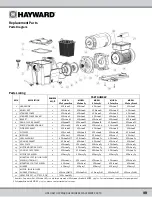


USE ONLY HAYWARD GENUINE REPLACEMENT
PARTS
5
Installation Instructions
NOTICE
–
This product should be installed and serviced only by a qualified professional.
Pump
Location
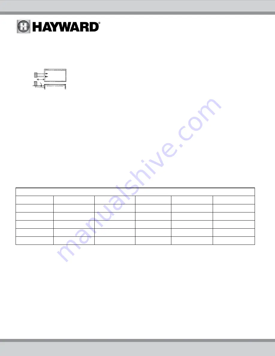
Locate pump as close to pool as practical and run suction lines as direct as possible to reduce
friction loss. Suction lines should have continuous slope upward from lowest point in line.
Joints must be tight (but not over-tightened). Suction line diameter must equal or be larger than
the discharge line diameter.
Though the pump is designed for outdoor use, it is strongly advised to protect the electrical components from the
weather. Select a well-drained area, one that will not flood when it rains. Do NOT install pump in a damp or non-
ventilated location. Keep motor clean. Pump motors require free circulation of air for cooling.
Pump Mounting
Install pump on a firm, level base or pad to meet all local and national codes. Fasten pump to base or pad with
screws or bolts to reduce vibration and stress on pipe or hose joints. The base MUST be solid, level, rigid, and
vibration free.
Pump mount must:
Allow pump inlet height to be as close to water level as possible.
Allow use of short, direct suction pipe (to reduce friction losses).
Allow for ball valves in suction and discharge piping.
Be protected from excess moisture and flooding.
Allow adequate access for servicing pump and piping.
Incorporate a straight portion of pipe prior to pump inlet no less than (5) pipe diameters in length.
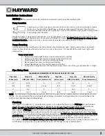
Pipe Sizing Chart
MAXIMUM RECOMMENDED SYSTEM FLOW RATE BY PIPE SIZE
Pipe Size
Flow rate
Water Velocity
Pipe Size
Flow rate
Water Velocity
inches [mm]
GPM [Liter/Min]
ft/sec [meters/sec]
inches [mm]
GPM [Liter/Min] ft/sec
[meters/sec]
1 ½”
50.76
8
2 ½”
119
8
[50] [192] [2.44] [75] [452] [2.44]
2” 84 8 3” 184 8
[63] [317] [2.44] [90] [698] [2.44]
NOTE – System design should allow a maximum of 8-ft/sec [2.44 meters/sec] water velocity in residential pool or spa
piping. It is recommended that a minimum length of piping, equivalent to 10 pipe diameters, be used between the
pump suction inlet and any plumbing fittings.
Plumbing
When pump is installed in 1.5" pipe diameter system, use supplied bushing kit.
Use PTFE tape to seal threaded
connections on molded plastic components. All plastic fittings must be new or thoroughly cleaned before use.
NOTE - Do NOT use Plumber’s Pipe Dope as it may cause cracking of the plastic components.
When applying PTFE tape to plastic threads, wrap the entire threaded portion of the male fitting with one to two
layers of tape. Wind the tape clockwise as you face the open end of the fitting, beginning at the end of the fitting.
The pump suction and outlet ports have molded-in thread stops. Do NOT attempt to force hose connector fitting
past this stop. It is only necessary to tighten fittings enough to prevent leakage. Tighten fitting by hand and then
use a tool to engage fitting an additional 1 ½ turns. Use care when using PTFE tape as friction is reduced
considerably; do NOT over-tighten fitting or you may cause damage. If leaks occur, remove connector, clean off
old PTFE tape, re-wrap with one to two additional layers of PTFE tape, and re-install connector.


