Page
e 12 of 36
4.12.
Inte
The interfa
procedure
1.
TURN
2.
Loose
(Figur
3.
Disco
4.
Loose
moun
5.
Disco
Apply
6.
Moun
7.
Conne
sectio
suitab
motor
tight c
may b
8.
Moun
9.
Reinst
tighte
10.
Instal
protec
11.
Apply
The follow
rface Wal
ace can also b
e.
OFF THE ELEC
en the two scre
re 4.12-1)
nnect the sho
en the three sc
ting plate to g
nnect the sho
y electrical tap
t the wall mou
ect the interfa
on 5.2 to the m
ble for the inst
r drive and thr
cordgrip, appr
be up to 500 fe
t the user inte
tall the interfa
en the three sc
l the blank co
ct internal ele
y power to the
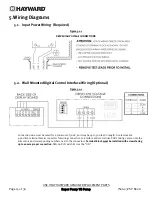
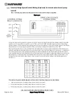
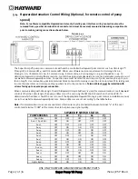
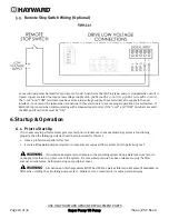
wing diagrams
Figur
USE ONLY H
l Mountin
be wall mount
CTRICAL POWE
ews securing
ort cable that e
crews securin
gain access to
ort cable on th
pe to the expo
unt plate, SP3
ace cable as sh
motor drive RS
tallation locat
rough the slot
ropriately size
eet in length.
erface to the w
ace mounting
crews to secur
over, SP3200D
ctronics. (Figu
system and re
s illustrate the
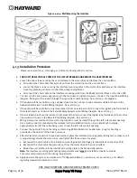
re 4.12-1: Rem
HAYWARD G
Super P
g
ted using the
ER AT THE CIR
the user inter
extends out fr
g the interface
o the drive wir
e interface m
sed conducto
3200DR10, in t
hown in the W
S485 terminal
tion. The cabl
t provided on
ed for the cabl
(Figure 4.12-4
wall mount pla
plate, taking
re.
DR9, on the mo
ure 4.12-3)
esume norma
interface wal
moving the Dig
GENUINE RE
Pump VS Pu
parts supplied
RCUIT BREAKE
rface to the mo
rom the motor
e mounting pl
ring compartm
ounting plate
ors. (Figure 4.1
the desired lo
Wall Mounted
block and use
e must be rou
the backside
le being used
4)
ate, SP3200D
care to make
otor drive in t
al operation.
ll mounting pr
gital Control I
PLACEMENT
ump
d in the optio
R.
otor drive and
r drive to the u
late to the mo
ment. (Figure 4
from the RS4
12-2)
ocation. (Figur
Digital Contro
er interface PC
uted through t
of the wall mo
, to seal the le
R10, using the
sure it is prop
he desired ori
rocedure.
nterface for W
T PARTS
nal wall moun
d remove the u
user interface
otor drive and
4.12-2)
485 terminal b
re 4.12-4)
ol Interface Wi
CB. Use multi
the left side co
ount plate, SP
eft side condu
e two screws.
perly aligned w
ientation. Thi
Wall Mounting
IS2603V
nt kit using th
user interface
. (Figure 4.12-
remove the in
block on the d
iring diagram
-conductor, ja
onduit openin
P3200DR10. U
uit opening. C
(Figure 4.12-4
with the moto
is cover is imp
g
VSP Rev-A
e following
e.
-1)
nterface
rive PCB.
shown in
acketed cable
ng on the
Use a liquid
Cable used
4)
or drive, and
portant to


