USE ONLY HAYWARD GENUINE REPLACEMENT PARTS
Page 18 of 36
2.70 THP VS Pump Family
IS3206VSP3 Rev-B
5.5.
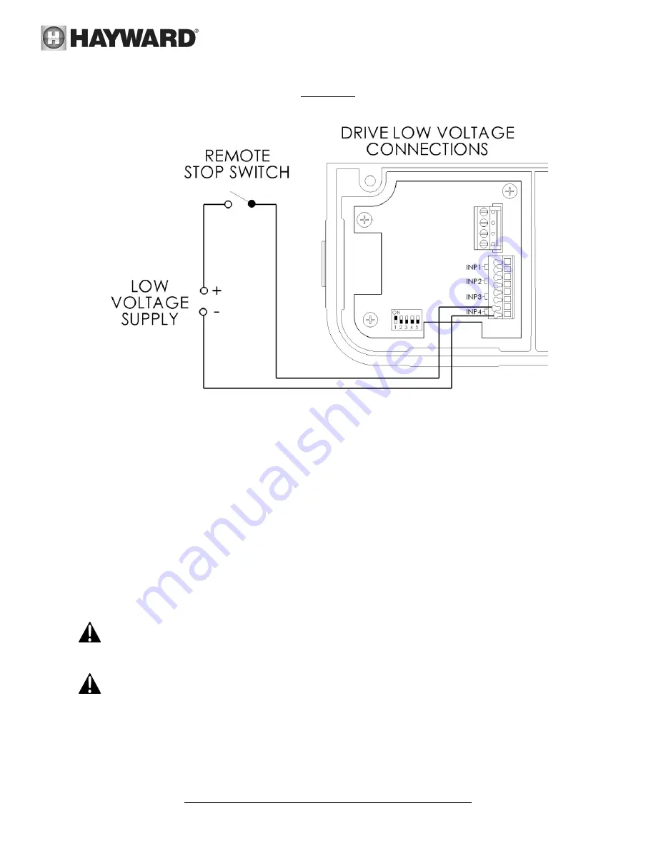
Remote Stop Switch Wiring (Optional)
Figure 5.5-1
Connection wire must be rated for a minimum of 300V. Switch must be latching type; pump is stopped when circuit is
closed. Inputs are rated to accept a low voltage supply of 18-30 VAC, 9-30 VDC, 50/60 Hz. The “+12V” and “COM”
terminals may be used as a low voltage supply, however these terminals also supply power to the user interface , so
care must be taken when connecting to these terminals to ensure proper operation of user interface. If the “+12V” and
“COM” terminals are used, DIP switch #1 must be “ON”.
6.
Startup & Operation
6.1.
Prior to Start-Up
If it is necessary to perform a water pressure test prior to initial use to ensure plumbing system is functioning
properly, then the following criteria should be maintained for this test:
1.
Have a professional perform this test.
2.
Ensure all Hayward pump and system components are removed from system prior to performing test.
WARNING
– If circulation equipment must remain in the plumbing system during water pressure test, do
not apply more than 10 psi pressure to the system. Be sure water pressure has been released, using the filter
manual air relief valve, before removing pump strainer cover.
WARNING
– All suction and discharge valves MUST be OPEN, as well as filter air relief valve (if available) on
filter, when starting the circulating pump system. Failure to do so could result in severe personal injury.


