Diagnostics
1.
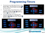
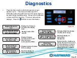
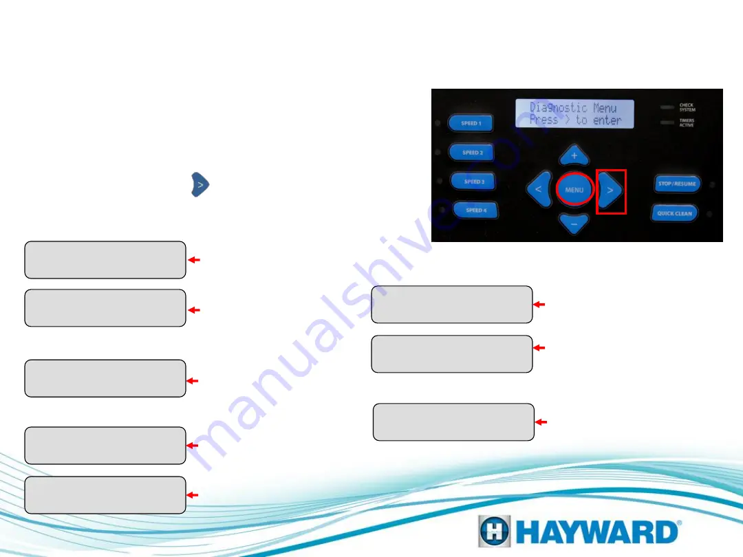
Press the Menu button until the Diagnostic screen
appears
(fig 54).
This menu provides important
information about the performance of the pump that can
be used during troubleshooting. Below are the different
screens and their meaning. These are all real-time
displays. Press the button to view information.
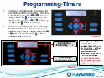
Display Revision
1.01
Drive Serial Number
DET-3581200032
DC Bus Voltage
Within Range
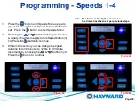
Motor Current
1.1A (8.5A Max)
Power Usage
225W (1700W Max)
Comm Rev: 0.96
Drv Rev: 2.00
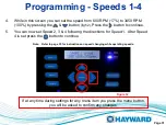
Drive Temperature
67
°
C (110
°
C Max)
Event Log
Press + to View
Displays motor drive
serial #.
Displays status of internal
DC bus voltage.
Real-time display of
motor input current.
Estimated Real-time display
of pump power usage.
Real-time display of
motor driver
temperature.
By pressing the + button you
will see the last 20 errors and
or trip conditions, as well as
the amount of time that has
elapsed since the condition
occurred.
Page 35
Figure 54
Displays the firmware
revision of the display
PCB.
Displays firmware
revisions of the motor
drive and drive
communication PCBs.