ULTRA-PRO
LX
PUMP MECHANICAL TIMER MODULE INSTRUCTIONS
Your integrated timer module is preprogrammed to operate your filtration system for nine
(9) hours – one five hour period and one four hour period during the day.
All you have to do is set the correct time (Step 2) and plug in. If you prefer customizing
your settings, follow Steps 1-5.
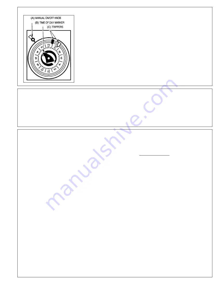
To Set Timer: (See Illustration)
1. To remove ON/OFF trippers, pull out completely from timer dial and then insert ON (red)
and OFF (white) trippers (C) into dial at desired ON and OFF times (if only one setting is
desired, remove the extra ON and OFF tripper from the dial).
2. Turn dial CLOCKWISE one or more complete revolutions until the exact time-of-day is
to the time-of-day marker (A).
3. FOR EARLY ON OR OFF OPERATION: Turn manual knob (B) counter clockwise to
desired ON or OFF position. Timer will follow next scheduled automatic operation.
4. Close cover after setting.
5. Plug in Pump/Timer unit.
IN CASE OF POWER FAILURE, RESET TIMER, (SEE STEP 2)
WARNING: THIS SWIMMING POOL PUMP TIMER IS INTENDED FOR USE ON
A.O. SMITH, 115 VOLT MOTORS ONLY UP TO 16 FULL LOAD AMPS.
01. Turn off power and unplug power cord. Remove pump
and motor assembly from piping system. (If optional
elevated mounting base was installed, pump assembly
can be disengaged from elevated base by depressing
spring catch on top of base, and sliding pump assembly
out to the rear).
02. Remove motor housing end cover by removing two (2)
screws. Carefully pull cover away from motor and
disconnect wires from motor terminals.
03. Remove pump housing cover (with strainer attached)
by removing the eight (8) housing bolts and nuts which
fasten housing cover to pump housing. The impeller is
now exposed.
04. To remove impeller, insert screwdriver in slot at end of
motor.* Hold screwdriver so as to keep shaft from
turning, and rotate the impeller in a counterclockwise
direction. The spring portion of the seal assembly is
now exposed.
05. Note carefully the position of the spring seal and pull it
off the impeller.
06. To remove the stationary (ceramic seat) part of the seal
assembly:
a. Loosen the four (4) motor securing bolts and
disengage the motor, with motor housing in place,
from the pump housing.
b. With motor removed, press the clear plastic and
ceramic seat assembly out of the pump housing
recess. If tight, tap lightly from the "motor" side.
07. Clean and lubricate the impeller hub shaft and pump
housing seal recess. Use silicone or Jack's No. 327 O-
Ring lube. Gently wipe the polished face of the new
ceramic seat with a soft, dry cotton cloth.
08. Press the new spring portion of the assembly onto the
impeller, black polished surface facing away from the
impeller.
09. Be sure black rubber O-Ring is in place on cut ridge of
clear plastic seat retainer. Press plastic retainer, with
ceramic seat inside, into recess of pump housing - O-
Ring end first. Seat the assembly firmly and evenly,
using finger pressure.
10. Carefully insert the motor shaft thru the seat assembly,
and secure motor and motor housing to pump housing
with four (4) motor securing bolts. (Be sure motor
housing mounting bracket is positioned properly.
11. Screw the impeller, with spring seal, onto the motor
shaft, hand tight, by turning clockwise.
12. Clean housing O-Ring (replace if necessary) and fasten
housing cover to pump housing with eight (8) bolts and
nuts. Tighten bolts and nuts alternately and evenly.
13. Reconnect electric wires from power cord and timer to
pump motor terminals. Both white wires to line 2; both
black wires to A; red timer wire to line 1. Ground wire to
ground screw on motor. Replace cover and secure with
two (2) screws.
14. Reconnect pump to piping system. Be sure to fill
strainer with water before restarting.
SEAL CHANGE INSTRUCTIONS
Exercise extreme care in handling and installing the new seal and seat assembly.
The lapped and polished surfaces may easily be damaged by dirt or scratching.
For safety, all service must be performed with all power shut off.
ELECTRONIC TIMER MODULE INSTRUCTIONS
Your integrated timer module is designed to be programmed to your filtration need, with four (4) possible settings.
Settings:
Setting 1 - Pump runs 24 hours continuously - (1 beep)
Setting 2 - Pump runs 18 hours and is off for 6 hours - (2 beeps)
Setting 3 - Pump runs 12 hours and is off for 12 hours - (3 beeps)
Setting 4 - Pump runs 6 hours and is off for 18 hours - (4 beeps)
When the pump is switched from position “off” to “program” a beep sound
is heard. This allows the pumps to differentiate between settings.
To Set Timer:
1. Move switch from “off” to “program” to “off” produces 1 beep
2. Move switch from “off” to “run”
3. Repeat above 2 steps according to your choice of setting
If a power failure occurs: After the power is restored, the timer will
automatically default to the programmed mode, adding the length of time
of the power failure.
*For A.O. Smith Motors: Carefully apply wrench to flat on rear motor shaft to hold shaft from turning.


