HAZET-WERK
Hermann Zerver GmbH & Co. KG
;
Güldenwerther Bahnhofstrasse 25 – 29 · 42857 REMSCHEID · GERMANY
[
+49 (0) 21 91 / 7 92-0 ·
\
+49 (0) 21 91 / 7 92-375 ·
^
hazet.de ·
]
info@hazet.de
HAZET-WERK
Hermann Zerver GmbH & Co. KG
;
Güldenwerther Bahnhofstrasse 25 – 29 · 42857 REMSCHEID · GERMANY
[
+49 (0) 21 91 / 7 92-0 ·
\
+49 (0) 21 91 / 7 92-375 ·
^
hazet.de ·
]
info@hazet.de
•
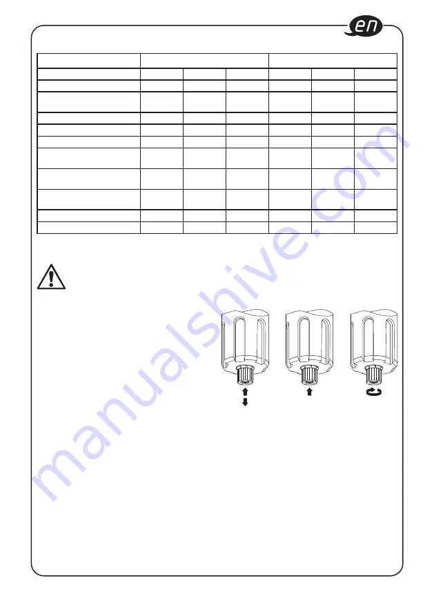
Condensate drain
There is a condensate drain valve
4
in the lower
part of the filter cup.
1
2
3
• Position
1
– semi-automatic condensate drain:
The valve knob is in central free position
– valve closes if system is under pressure,
condensate is drained only during the
absence of pressure
• Position
2
– manual condensate drain:
Push the valve knob up to drain condensate
manually even under pressure.
• Position
3
– manual valve closing:
Turn the valve knob counterclockwise to close
valve manually.
Please take care to drain the condensate regularly
9. Before starting the operation
Note:
Prior to installation, please observe the
air flow direction marked by arrows
• The filter-pressure reducer is equipped with a front
and a rear outlet for the manomenter. Close the
outlet not being used with the threaded plug
8
• Before pressurizing the system, fill the lubricator
with oil either directly by unscrewing the oil-cup
7
or through the oil filler plug
6
positioned on top of
the lubricator body.
Only use ISO and UNI FD oils.
10. Application
•
Air pressure adjusting:
By operating the pressure regulator
2
on top of
the filter-pressure reducer
1. Raise the pressure regulator knob
2
upwards
in order to permit rotation
2. Increase pressure: turn the knob clockwise
decrease pressure: turn the knob
counterclockwise
3. Once the desired pressure has been obtained,
push the knob downwards in order to lock it in
place.
4. With a final clockwise rotation the desired
pressure is built-up.
8. Technical data
Maintenance Unit
Filter-Pressure Reducer
9070-2
9070-3
9070-4
9070-5
9070-6
9070-7
Connecting thread
1
⁄
2
˝
3
⁄
8
˝
1
⁄
4
˝
1
⁄
2
˝
3
⁄
8
˝
1
⁄
4
˝
Flow rate at 6.3 bar
Nl/min
5000
5000
1800
5000
5000
1800
Working pressure max. bar
12
12
10
12
12
10
Pressure max.
bar
16
16
12
16
16
12
Pressure indication
bar
0,5 – 12
0,5 – 12
0,5 – 10
0,5 – 12
0,5 – 12
0,5 – 10
Permissible temperatur
range °C
-10 up to
+55
-10 up to
+55
-10 up to
+55
-10 up to
+55
-10 up to
+55
-10 up to
+55
Filter-Pressure Reducer
Capacity ml
50
50
30
50
50
30
Oil-cup
Capacity ml
170
170
40
–
–
–
Oil filter element
mm
10
10
10
10
10
10
Manometer connection
1
⁄
8
˝
1
⁄
8
˝
1
⁄
8
˝
1
⁄
8
˝
1
⁄
8
˝
1
⁄
8
˝


