background image

10 

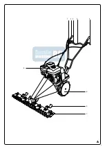
DESCRIPTION (FIG. A)

This machine is designed for mowing lawns in residential gardens. The machine is 
not suitable for commercial use.

1.  Throttle
2.  Handle
3.  Clutch lever forward
4.  Handle
5.  Reverse clutch lever
6.  Wheel
7.  Cutter bar
8.  Enginer
9.  Height guide

PACKAGE CONTENTS

• Scythe mower
• 2 wheels
• Cutter bar
• Long bolt with tappered locking nut

•  Spark plug wrench
• Oil syringe
• Bolts and nuts

IMPORTANT

First install the machine and then fill the gearbox with 150 ml of gear oil. Use the 
supplied oil syringe for this. Filling the gearbox with gear oil is necessary to prevent 
the gears from wearing out within 5 minutes of use. Gear wear, caused by direct 
use without topping up gear oil, is not covered by the warranty.

ASSEMBLING 

The trencher is supplied partially assembled. 

TOOLS NEEDED

• Spanner 17 mm
• Open-end wrench 14 mm
• Open-ended or socket wrench 10 mm
• Open-end or socket wrench 8 mm
• Socket wrench 14 mm
• Socket wrench 17 mm
• Socket wrench holder with ratchet

   To simplify installation, follow the order below.

MOUNTING THE WHEELS IN FREEWHEEL POSITION

1.  Slide a wheel tube onto the wheel axle as far as possible.
2.  Insert a locking pin only through the wheel axle.
3.  Press the lock onto the locking pin.

Assembly of the handle
Slide the handlebar support over the handlebar holder. Insert the supplied bolt 
through the round holes and screw the tapered locking nut (with the narrow side 
toward the handlebar) onto the bolt. Lock the handlebar by pushing the cam on the 
tapered nut into the recess.

MOUNTING THE HEIGHT GUIDES

1.  Place the height guide brackets on the cutter bar.
2.  Place a lock washer and spring washer over the 4 bolts.
3.  Screw on with 4 nuts. Use a spanner and a socket wrench to fix the cutter bar.
4.  Insert a bolt from below through a bracket and a height guide and secure with

a nut, lock washer and spring washer.

MOUNTING THE CUTTER BAR

1.  Check that the drive ring is placed on the eccentric shaft.
2.  Insert 4 bolts from bottom to top through the cutter bar.
3.  Place the machine with the drive ring in the guide over the 4 bolts on the

cutter bar.

4.  Place a lock washer and spring washer over the 4 bolts.
5.  Screw on the cutter bar with 4 nuts. Use a spanner and a socket wrench to fix

the cutter bar.

6.  Apply a liberal amount of grease to the eccentric shaft and guide.

BEFORE FIRST USE

THE MOTOR (FIG. B)

A  Air filter
B Muffler
C  Spark plug
D Throttle
E  Pull starter
F  Motor switch
G  Start cord
H  Fuel tap
J  Choke lever
K  Fuel cap
L  Petrol tank
M Dipstick
N  Drain plug

    These machines are supplied without fuel and oil. Fill, before use, fuel and 

oil to the correct level. Operating the machine without or with too little oil 
can cause serious engine damage that is not covered by the warranty.

FILLING UP WITH FUEL

Always use fuel that meets the following specifications: unleaded petrol, minimum 
octane rating 86.

    Never top up with fuel while the machine is running. Allow the machine to 

cool for at least 15 minutes after filling up before adding fuel.

  Do not smoke near the machine or near the fuel. Never add fuel in the 

vicinity of sparks, flames or open flames.

• Remove the cover (K) from the filling opening.
• Carefully pour the fuel into the filling opening. Do not fill the tank beyond the top

of the fuel filter.

• Replace the lid on the filling opening.

FILLING WITH ENGINE OIL

Use 4-stroke engine oil. SAE 10W-30 is suitable for general use at all 
temperatures. Other viscosity can be used when the average ambient temperature 
is within it specified ranges.
• Remove the dipstick (M) from the filling point.
• Fill the crankcase with the specified amount of oil.
• Refit the dipstick.

USE

DRIVE

The gearbox is filled with oil at the factory.

ADJUSTING THE HANDLE HEIGHT

1.  Loosen the tapping nut on the handlebar holder.
2.  Adjust the height of the handlebar.
3.  Retighten the bolt and push the cam back into the recess

ADJUSTING THE CUTTING HEIGHT

The cutting height can be adjusted with the height guides (9).
1.  Loosen the nuts.
2.  Slide the height guides to the desired height.
3.  Retighten the nuts.

    Always set both height guides to the same height.

ADJUSTING THE WHEELS IN THE DRIVING POSITION

1.  Pull the locking pin out of the wheel axle.
2.  Slide the wheel tube back so that the holes in the wheel tube match the holes

in the wheel axle.

3.  Insert a locking pin through the wheel tube and the wheel axle.
4.  Press the lock onto the locking pin. 

STARTING THE ENGINE (FIG. A + B)

   Always start the machine at the job site and allow it to warm up. With the 

machine running, check that all controls are working properly before 
using it.


Summary of Contents for 57091HBM

Page 1: ...57091HBM INSTRUCTION MANUAL MANUEL D UTILISATION ANLEITUNG INSTRUCCIONES ISTRUZIONI FR DE ES IT PROFESSIONAL BARRE DE FAUCHAGE BALKENM HER CORTADORA DE GUADA A FALCIATRICE BG EN...

Page 2: ...2 5 ENGLISH 9 FRAN AIS 13 DEUTSCH 17 ESPA OL 21 ITALIANO 25 31...

Page 3: ...3 A 2 3 4 5 6 9 7 1 8...

Page 4: ...4 B A D K L M N B E G H F C J...

Page 5: ...5 NEDERLANDS a 5 5...

Page 6: ...6 20 A 1 2 3 4 5 6 7 8 9 2 2 150 5 17 14 10 8 14 17 1 2 3 1 2 4 3 4 4 1 2 4 3 4 4 4 5 4 6 B A B C D E F G H J K L M P 86 15 K 4 SAE 10W 30 M 1 2 3 9 1 2 3...

Page 7: ...7 NEDERLANDS 1 2 3 4 A B 1 H ON 2 J CHOKE 3 D R 4 F ON G 5 RUN 6 3 4 1 R A 1 2 2 3 A 1 2 2 5 3 A 1 1 1 A B 1 L F OFF 1 2 3 4 1 2 3 20 100 6 50 A C 0 6 0 8 mm...

Page 8: ...8 5 20 3 50 6 100 12 300 x x x x x x x x x x x x 57091HBM pk 7 cm 100 mm 10 80 3 50 6 OHV 4 takt cc 208 l 3 6 l 0 6 Euro 95 E10 SAE 10W 30 Start system F7TC kg 75 LWA dB A 112 KWA dB A 1 5 2002 96 EC...

Page 9: ...e exhaust from the engine contains carbon monoxide which is an odourless tasteless and a deadly poisonous gas Store all fuel and oil in containers specifically designed and approved for this purpose a...

Page 10: ...Use a spanner and a socket wrench to fix the cutter bar 6 Apply a liberal amount of grease to the eccentric shaft and guide BEFORE FIRST USE THE MOTOR FIG B A Air filter B Muffler C Spark plug D Thro...

Page 11: ...ge the oil Cover the machine and place it in a clean and dry environment CLEANING AND MAINTENANCE Regular cleaning and maintenance are essential for the machine to function properly and for a long ser...

Page 12: ...acy KWA dB A 1 5 Take appropriate measures for the protection of hearing The sound levels stated are emission levels they are not necessarily safe working levels Even though the measured values are re...

Page 13: ...cette machine Vous devez tous moments viter la zone de dangers quand la machine est en fonctionnement Veillez ce que personne ne travaille sous ou proximit de la machine avant de d marrer le moteur ou...

Page 14: ...GE DE LA POIGN E Faites glisser le support du guidon sur le socle du guidon Ins rez le boulon fourni dans les trous ronds puis vissez le contre crou fusel avec le c t troit orient vers le guidon sur l...

Page 15: ...bas NETTOYAGE DE LA BARRE DE COUPE La barre de coupe doit tre nettoy e apr s utilisation 1 D montez la lame en desserrant tous les boulons 2 Lubrifiez toutes les pi ces mobiles avec un lubrifiant biod...

Page 16: ...ys d utilisation Ces informations sont uniquement destin es aider les utilisateurs valuer les risques ventuels GARANTIE Pour les clauses de garantie reportez vous aux conditions de garantie ci jointes...

Page 17: ...hine in Betrieb ist muss der Gefahrenbereich immer vermieden werden Sorgen Sie daf r dass vor dem Start oder Transport der Maschine niemand unter oder in der Umgebung der Maschine arbeitet Sorgen Sie...

Page 18: ...stift durch die Radachse 3 Dr cken Sie das Schloss auf den Sicherungsstift MONTAGE DES GRIFFS Schieben Sie die St tze ber die Halterung des Handgriffs F hren Sie die mitgelieferte Schraube durch die r...

Page 19: ...ne rutscht bewegt sich die Stellmutter am Kabel nach oben Wenn der Balkenm her danach nicht stoppt l sen Sie den Kupplungshebel und drehen Sie die Stellmutter nach unten M HBALKEN REINIGEN Der M hbalk...

Page 20: ...HNISCHE DATEN 57091HBM Max Leistung PS 7 0 Schnittbreite cm 100 Schnitth he mm 10 80 Reifendruck 3 5 6 Motor 4 Takt OHV Motor Motorleistung ccm 208 Benzinvolumen l 3 6 ltankvolumen l 0 6 Benzin bleifr...

Page 21: ...en contacto con las autoridades de obras p blicas de su municipio y con los proveedores de servicios para conocer las ubicaciones de las tuber as y cables subterr neos cuando proceda antes de poner en...

Page 22: ...3 Enrosque con 4 tuercas Utilice una llave inglesa y una llave de tubo para sujetar la barra cortadora 4 Inserte un perno desde la parte inferior atravesando una abrazadera y una gu a de altura y suj...

Page 23: ...MACENAMIENTO La m quina est dise ada para transportarse en furgoneta o en un cami n peque o La m quina solo puede elevarse con las herramientas correspondientes o con un n mero suficiente de personas...

Page 24: ...12 Imprecisi n de las mediciones KWA dB A 1 5 Adopte las medidas oportunas de protecci n auditiva Los niveles de sonido indicados son niveles de emisi n y no son niveles de trabajo necesariamente segu...

Page 25: ...e cavi sotterranei ove applicabile prima di utilizzare la macchina SICUREZZA DEI CARBURANTI La benzina un liquido altamente infiammabile La benzina emette anche vapori infiammabili che possono prender...

Page 26: ...chiave esagonale per fissare la barra falciante 4 Inserire un bullone dal basso attraverso una staffa e una guida per l altezza e fissarlo con un dado una rondella di sicurezza e una rondella elastic...

Page 27: ...na Se la macchina viene messa fuori servizio per un periodo di tempo prolungato necessario svuotare il serbatoio del carburante e cambiare l olio In questo modo si evitano problemi durante il riavvio...

Page 28: ...tica dB A 112 Incertezza di misurazione KWA dB A 1 5 Adottare misure adeguate per la protezione dell udito I livelli acustici indicati sono livelli di emissione non sono necessariamente livelli di lav...

Page 29: ...29 ITALIANO 30 10 15 1 2 3 4 4 1 4 2 4 3 4 4 4 5 4 6 5 5 1 5 2 5 3 5 4 5 5 6...

Page 30: ...30...

Page 31: ...B V declara bajo su exclusiva responsabilidad que este producto es conforme con las siguientes normas o documentos de normalizaci n HBM Machines B V dichiara sotto la propria responsabilit che il pre...

Page 32: ...HBM Machines B V Grote Esch 1010 2841 MJ Moordrecht The Netherlands www hbm machines com...

Reviews: