15
RSCC
A3018-3.2 en/de/fr
HBM
leads due to the cable resistance that is still present and not compensated for
by
the six‐wire configuration. A large part of this loss can be eliminated by a
calibration, however
, the temperature‐dependent part remains. The TK
c
value
given in the specifications for the transducer therefore does not apply for the
cable and transducer combination when connection is in a four‐wire
configuration, as here the cable percentage must be added.
6.3 Extension cable
The
cable of a six‐wire load cell such as the RSCC can be extended with a
cable of the same type.
Only
use shielded, low‐capacitance measurement cables for extension.
Ensure that connection is perfect, with a low contact resistance.
6.4 Cable protection
The transducers attain protection class IP68 as per DIN EN 60529. In
applications where the PVC cable of the load cell can be chemically or
mechanically attacked or destroyed, extra cable protection must be provided
by means of standard cable protection systems. The load cell can be fitted
with an adapter with an internal M12 thread (optional “with cable protection
system adapter" version) for mounting the screwed cable gland of the flexible
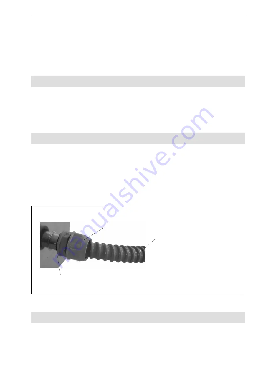
cable protection tubing. Fit the cable protection system as shown in Fig. 6.2.
Cable protection system* (provided by customer), comprising:
* Supplier such as Flexicon
)
Screwed cable gland*
Flexible cable protection tubing*
O‐ring
(provided by customer)
Unscrew the M12 sleeve and replace
with an M12 threaded tube coupling
Fig. 6.2:
Cable protection (implemented by the customer)
6.5 EMC protection
Electrical and magnetic fields often induce interference voltages in the
measuring circuit. Therefore:
Summary of Contents for 1-U1R/200KG/ZGW
Page 2: ...English Page 3 20 Deutsch Seite 21 38 Fran ais Page 39 53...
Page 58: ...RSCC 58 A3018 3 2 en de fr HBM...
Page 59: ......

