background image

17

RSCC

A3018-3.2  en/de/fr

HBM

7

Specifications

Type

RSCC

Accuracy class as per OIML R 60

No. of load cell verification intervals (n

LC

)

C3

3000

Maximum capacity (E

max

)

50 kg 100 kg 200 kg 500 kg 1 t

2 t

5 t

Minimum load cell verification

interval (v

min

)

%


of E

max

0.0120

Nominal (rated) sensitivity (C

N

)

mV/V

2

Sensitivity tolerance

%

"

0.25

Zero signal

mV/V

"

0.1

Temperature coefficient of

sensitivity (TK

C

)

1)

% of C

/

10 K

"

0.0170 (20

C to 40

C)

"

0.0110 (-10

C to 20

C)

Temperature coefficient of zero

signal (TK

0

)

"

0.0166

Rel. reversibility error (d

hy

)

1)

% of C

n

"

0.0166

Non‐linearity 

(d

lin

)

1)

"

0.0166

Creep upon loading (d

cr

) over

30 min.

"

0.0166

Input resistance (R

LC

) (nom.)

389 

"

15

Output resistance (R

0

)

350 

"

1.5

Insulation resistance (R

iso

)

G

/100 V

> 2

Reference excitation voltage

(U

ref

)

Nominal (rated) supply voltage

range (B

U

)

V

5

0.5 to 12

Nominal (rated) ambient

temperature range (B

T

)

C

-10  to  +40

Operating temp. range (B

tu

)

-30  to  +70

Storage temperature range (B

tl

)

-50  to  +85

Reference temperature (t

ref

)

22

Limit load (E

L

)

%


of E

max

150

Breaking load (E

d

)

200

300

200

Relative perm. vibrational

stress (F

srel

) (oscillation width

as per DIN 50100)

70

Nom. (rated) displacement at

max. capacity (s

nom

"

0.05 mm

mm

0.35

0.4

0.35

0.1

0.2 0.2 0.4

Weight (G), approx.

kg

0.7

1

1.4

1.7 2.2

Degree of protection per EN 60

529 (IEC 529)

IP 68 (test conditions 1 m water column / 100 h)

Cable 

length, six‐wire

configuration

7.6 m as standard

Material:

Measuring body

Cable entry

Cable sheath

stainless steel 

2)

stainless steel / neoprene

PVC

1)

The values for 

non‐linearity

 (d

lin

), relative reversibility error (d

hy

) and temperature coefficient of sensitivity (TK

C

) are recommended values.

The sum of these values is within the cumulated error limits according to OIML R60.

2)

As per EN 10088-1.

See data sheet for options.

Summary of Contents for 1-U1R/200KG/ZGW

Page 1: ...A3018 3 2 en de fr Load cells W gezellen Pesons RSCC Mounting Instructions Montageanleitung Notice de montage...

Page 2: ...English Page 3 20 Deutsch Seite 21 38 Fran ais Page 39 53...

Page 3: ...echanical installation 10 5 1 Mounting instructions 10 5 2 Load application 11 5 3 Mounting with knuckle eyes 11 6 Electrical connection 14 6 1 Connection in a six wire configuration 14 6 2 Connection...

Page 4: ...lls are not safety elements within the meaning of designated use For safe and trouble free operation transducers must not only be correctly transported stored sited and mounted but must also be carefu...

Page 5: ...o longer be used must be disposed of separately and not with normal household waste If you need more information about waste disposal please contact your local authorities or the dealer from whom you...

Page 6: ...ion regulations must be taken into account even though the breaking load is well in excess of the maximum capacity In particular you should take into account the following as quoted in the specificati...

Page 7: ...amic load measurements they must be handled very carefully Particular care must be taken when transporting and installing the devices Dropping or knocking the transducers may cause permanent damage Th...

Page 8: ...Moisture and other ambient conditions Series RSCC load cells are hermetically sealed and are therefore not at all sensitive to humidity and moisture The transducers attain protection class IP68 as per...

Page 9: ...3 2 en de fr HBM NOTE Measurement errors may be the result if dust or dirt is deposited inside the load cells The relevant areas are marked by arrows in Fig 4 1 Fig 4 1 Deposits at the marked areas mu...

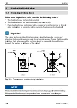
Page 10: ...owing over the load cell Important The cable fastening side of the transducer should always be connected directly with the rigid customer side force transfer areas Ensure that the cable is laid so tha...

Page 11: ...of torsional moments on the transducer and also when 2 knuckle eyes are used bending moments together with lateral and oblique loadings Mount the knuckle eyes applying pre stressing to the transducer...

Page 12: ...H min H max MB MB Rigid force transfer Fig 5 2 Installation with one knuckle eye Maximum capacity Knuckle eye Hmin Hmax Emin Emax MB NVm 50 kg 1 U1R 200KG ZGW 86 90 4 8 15 100 kg 1 U1R 200KG ZGW 86 90...

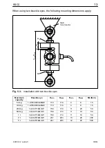
Page 13: ...5 3 Installation with two knuckle eyes Maximum capacity Knuckle eye Hmin Hmax Emin Emax MB NVm 50 kg 1 U1R 200KG ZGW 110 118 4 8 15 100 kg 1 U1R 200KG ZGW 110 118 4 8 15 200 kg 1 U2A 1T ZGUW 156 174...

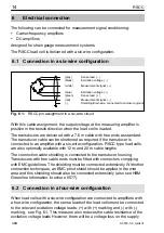
Page 14: ...tened as required if the transducer is connected to an amplifier with a six wire configuration RSCC type load cells are also optionally available with 12 m and 20 m cable lengths The connection cable...

Page 15: ...ransducers attain protection class IP68 as per DIN EN 60529 In applications where the PVC cable of the load cell can be chemically or mechanically attacked or destroyed extra cable protection must be...

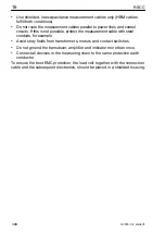
Page 16: ...tect the measurement cable with steel conduits for example Avoid stray fields from transformers motors and contact switches Do not ground the transducer amplifier and indicator more than once Connect...

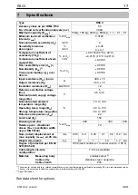
Page 17: ...upply voltage range BU V 5 0 5 to 12 Nominal rated ambient temperature range BT C 10 to 40 Operating temp range Btu 30 to 70 Storage temperature range Btl 50 to 85 Reference temperature tref 22 Limit...

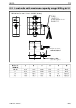
Page 18: ...ns in mm 1 mm 0 03937 inches Without adapter for cable protection system With adapter for cable protection system Length 7 6 m Outside diameter 5 mm Material PVC Cable D M M A B C 13 24 20 M12x1 5 Max...

Page 19: ...Without adapter for cable protection system With adapter for cable protection system Length 7 6 m Outside diameter 5 mm Material PVC Cable A M M D C B 13 E 20 M12x1 5 Maximum capacity A B C D E M 500...

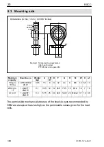
Page 20: ...mum capacity Knuckle eye Weight kg A jB H7 D F G H M W X a f 50 kg to 100 kg 1 U1R 200KG ZGW 0 05 15 8 24 32 44 9 M8 12 6 5 13 200 kg to 1 t 1 U2A 1T ZGUW 0 1 33 5 12 32 54 5 70 5 12 M12 16 7 19 2 t t...

Page 21: ...4 3 Ablagerungen 26 5 Mechanischer Einbau 28 5 1 Montagehinweise 28 5 2 Lasteinleitung 29 5 3 Montage mittels Gelenk sen 29 6 Elektrischer Anschluss 32 6 1 Anschluss in Sechsleiter Technik 32 6 2 Ans...

Page 22: ...ung von Zubeh r Die W gezellen sind keine Sicherheitselemente im Sinne des bestimmungs gem en Gebrauchs Der einwandfreie und sichere Betrieb des Aufnehmers setzt sachgem en Transport fachgerechte Lage...

Page 23: ...utz und Rohstoffr ckgewinnung getrennt von regul rem Hausm ll zu entsorgen Falls Sie weitere Informationen zur Entsorgung ben tigen wenden Sie sich bitte an die rtlichen Beh rden oder an den H ndler b...

Page 24: ...Mehrfaches der Nennlast betr gt m s sen die einschl gigen Unfallverh tungsvorschriften der Berufsgenossen schaften ber cksichtigt werden Ber cksichtigen Sie insbesondere die in den technischen Daten...

Page 25: ...chtige Handhabung Besondere Aufmerksamkeit erfordern hierbei Transport und Einbau der Ger te St e oder St rze k nnen zu permanenten Sch den am Aufnehmer f hren Die Grenzen f r die zul ssigen mechanisc...

Page 26: ...htigkeit und sonstige Umgebungsbedingungen Die W gezellen der Serie RSCC sind hermetisch gekapselt und deshalb sehr unempfindlich gegen Feuchteeinwirkung Die Aufnehmer erreichen die Schutzklasse IP68...

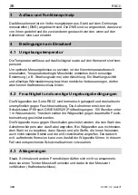
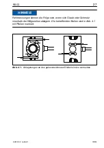
Page 27: ...EIS Fehlmessungen k nnen die Folge sein wenn sich Staub oder Schmutz innerhalb der W gezellen ablagern Die betreffenden Stellen sind in Abb 4 1 mit Pfeilen markiert Abb 4 1 Ablagerungen an den gekennz...

Page 28: ...W gezelle flie en k nnen Wichtig Die Kabelbefestigungsseite des Aufnehmers sollte immer direkt mit den star ren kundenseitigen Kraftausleitungsbereichen verbunden sein Achten Sie darauf dass das Kabe...

Page 29: ...von Torsionsmomenten und bei Verwendung von zwei Gelenk sen auch von Biegemomenten sowie Quer und Schr gbelastungen in den Aufnehmer Montieren Sie die Gelenk sen unter Einbringen einer Vorspannung in...

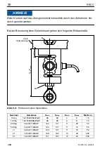
Page 30: ...uma e E min E max H min H max MB MB starre Kraftausleitung Abb 5 2 Einbau mit einer Gelenk se Nennlast Gelenk se Hmin Hmax Emin Emax MB NVm 50 kg 1 U1R 200KG ZGW 86 90 4 8 15 100 kg 1 U1R 200KG ZGW 86...

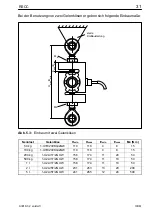
Page 31: ...leitung Abb 5 3 Einbau mit zwei Gelenk sen Nennlast Gelenk se Hmin Hmax Emin Emax MB NVm 50 kg 1 U1R 200KG ZGW 110 118 4 8 15 100 kg 1 U1R 200KG ZGW 110 118 4 8 15 200 kg 1 U2A 1T ZGUW 156 174 11 20 5...

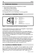
Page 32: ...ei einem Anschluss des Aufnehmers an Verst rker in Sechsleiter Technik k nnen Sie das Kabel des Aufnehmers bei Bedarf k rzen Optional sind W gezellen vom Typ RSCC mit den Kabell ngen 12 m und 20 m erh...

Page 33: ...enden Sie nur abgeschirmte kapazit tsarme Messkabel zur Verl nge rung Achten Sie auf eine einwandfreie Verbindung mit geringem bergangs widerstand 6 4 Kabelschutz Die Aufnehmer erreichen die Schutzkla...

Page 34: ...lel zu Starkstrom und Steuerleitungen Falls das nicht m glich ist sch tzen Sie das Messkabel z B durch Stahlpanzerrohre meiden Sie Streufelder von Trafos Motoren und Sch tzen erden Sie Aufnehmer Verst...

Page 35: ...der Versorgungs spannug BU V 5 0 5 12 Nennbereich der Umgebungs temperatur BT C 10 40 Gebrauchstemp bereich Btu 30 70 Lagerungstemp bereich Btl 50 85 Referenztemperatur tref 22 Grenzlast EL v Emax 150...

Page 36: ...g bis 200 kg Abmessungen in mm ohne Adapter f r Kabelschutzsystem mit Adapter f r Kabelschutzsystem L nge 7 6 m Au endurchmesser 5 mm Werkstoff PVC Kabel D M M A B C 13 24 20 M12x1 5 Nennlast A B C D...

Page 37: ...ohne Adapter f r Kabelschutzsystem mit Adapter f r Kabelschutzsystem L nge 7 6 m Au endurchmesser 5 mm Werkstoff PVC Kabel A M M D C B 13 E 20 M12x1 5 Nennlast A B C D E M 500 kg 87 3 57 2 28 6 43 7 3...

Page 38: ...Gewicht kg A jB H7 D F G H M W X SW 50 kg 100 kg 1 U1R 200KG ZGW 0 05 15 8 24 32 44 9 M8 12 6 5 13 200 kg 1 t 1 U2A 1T ZGUW 0 1 33 5 12 32 54 5 70 5 12 M12 16 7 19 2 t 5 t 1 U2A 5T ZGUW 0 4 57 5 25 60...

Page 39: ...m canique 46 5 1 Instructions de montage 46 5 2 Application de charge 47 5 3 Montage via anneaux rotule 47 6 Raccordement lectrique 51 6 1 Raccordement en technique six fils 51 6 2 Raccordement en te...

Page 40: ...consignes de s curit correspondants Ceci s applique galement l utilisation des accessoires Les pesons ne sont pas des l ments de s curit au sens de l utilisation conforme Afin de garantir un fonction...

Page 41: ...ation qui si les dispositions relatives la s curit ne sont pas respect es peut avoir pour cons quence des d g ts mat riels NOTE Description d une situation pouvant causer des d g ts mat riels Eliminat...

Page 42: ...Elles doivent tre m me de juger avec certitude les r sultats de leur travail et le contenu de la pr sente notice de montage doit leur tre familier Pr vention des accidents Bien que la charge de ruptur...

Page 43: ...donc tre mani s avec pr caution Dans ce cadre le transport et le montage des appareils doivent tre r alis s avec un soin particulier Les chocs et les chutes risquent de provoquer un endommagement irr...

Page 44: ...er un shunt 4 2 Humidit et autres conditions ambiantes Les pesons de la s rie RSCC sont ferm s herm tiquement et sont donc particuli rement insensibles l humidit Les capteurs atteignent la classe de p...

Page 45: ...OTE Des erreurs de mesure peuvent se produire lorsque de la poussi re ou des salet s se d posent l int rieur des pesons Les zones concern es sont rep r es par des fl ches sur la Fig 4 1 Fig 4 1 viter...

Page 46: ...tout peson par toron en cuivre est n cessaire pour qu aucun courant de soudage ne puisse passer par le peson Important Le c t de fixation du c ble du capteur doit toujours tre reli directement aux zo...

Page 47: ...et de moment HBM recommande d utiliser des anneaux rotule Les anneaux rotule conviennent pour un usage avec une charge quasi statique charge altern e v10 Hz 5 3 Montage via anneaux rotule L emploi d...

Page 48: ...adm 3 Orienter l anneau rotule 4 Serrer le contre crou avec le couple indiqu ci apr s Charge nominale kg Filetage au niveau du peson Couple de serrage NVm 50 100 M8 15 200 1000 M12 50 2000 5000 M24x2...

Page 49: ...Fig 5 2 Montage avec un anneau rotule Charge nom Anneau rotule Hmin Hmax Emin Emax MB NVm 50 kg 1 U1R 200KG ZGW 86 90 4 8 15 100 kg 1 U1R 200KG ZGW 86 90 4 8 15 200 kg 1 U2A 1T ZGUW 122 131 11 20 50...

Page 50: ...ig 5 3 Montage avec deux anneaux rotule Charge nom Anneau rotule Hmin Hmax Emin Emax MB NVm 50 kg 1 U1R 200KG ZGW 110 118 4 8 15 100 kg 1 U1R 200KG ZGW 110 118 4 8 15 200 kg 1 U2A 1T ZGUW 156 174 11 2...

Page 51: ...capteur l amplificateur en technique 6 fils le c ble du capteur peut tre raccourci le cas ch ant Les pesons de type RSCC sont disponibles en option avec des c bles de 12 m et 20 m de long Le blindage...

Page 52: ...de contact 6 4 Protection du c ble Les capteurs atteignent la classe de protection IP68 selon DIN EN 60529 Dans le cadre d applications dans lesquelles le c ble en PVC du peson risque de subir une att...

Page 53: ...les c bles de mesure en parall le avec des lignes de puissance et de contr le Si cela n est pas possible prot ger le c ble de mesure par ex l aide de tubes d acier blind s viter les champs de dispers...

Page 54: ...lage nominale de temp rature ambiante BT C 10 40 Plage utile de temp rature Btu 30 70 Plage de temp rature de stockage Btl 50 85 Temp rature de r f rence tref 22 Charge limite EL d Emax 150 Charge de...

Page 55: ...Dimensions en mm sans adaptateur pour syst me de protection de c ble avec adaptateur pour syst me de protection de c ble Longueur 7 6 m Diam tre ext 5 mm Mat riau PVC C ble D M M A B C 13 24 20 M12x1...

Page 56: ...ur pour syst me de protection de c ble avec adaptateur pour syst me de protection de c ble Longueur 7 6 m Diam tre ext 5 mm Mat riau PVC C ble A M M D C B 13 E 20 M12x1 5 Charge nom A B C D E M 500 kg...

Page 57: ...e nom Anneau rotule Poids kg A jB H7 D F G H M W X s p 50 kg 100 kg 1 U1R 200KG ZGW 0 05 15 8 24 32 44 9 M8 12 6 5 13 200 kg 1 t 1 U2A 1T ZGUW 0 1 33 5 12 32 54 5 70 5 12 M12 16 7 19 2 t 5 t 1 U2A 5T...

Page 58: ...RSCC 58 A3018 3 2 en de fr HBM...

Page 59: ......

Page 60: ...y are not to be understood as express warranty and do not constitute any liability whatsoever nderungen vorbehalten Alle Angaben beschreiben unsere Produkte in allgemeiner Form Sie stellen keine Besch...

Reviews: