background image

12

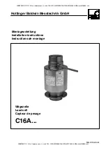
Wägezelle

Load cell

Capteur de pesage

C16A/...

Scope of supply

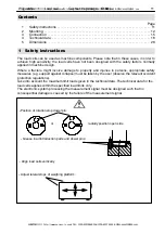
-- Pendle load cell with connection cable, dowel pin for rotation stop device up to a max. capacity

of 100t (load introduction parts as a separate order).

-- Mounting instructions

2 Mounting

General

D

Please handle the load cell carefully.

D

Use appropriate lifting gear when mounting the weighing device.

D

Do not overload the load cell, not even for a short time (e.g. due to unevenly distributed

bearing loads).

D

If required, use supporting elements (dummies) of the same height for alignment purposes.

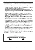
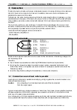
The C16 is a pendle load cell designed to automatically restore the mounting construction to a stable

initial position in the case of a lateral displacement or inclination of the load cell introduction. The

maximum permissible lateral displacement or inclination (refer to technical data) must not be

exceeded, otherwise the load cells or load introduction parts might be damaged. The easiest and

most common solution for this problem are the appropriate stops on the mounting construction

(weighing platform) which must be carefully adjusted within the specified values.

With the C16, we recommend the use of EPO3 and C16/EPU or C16ZOU44 mounting accessories

from HBM, because they permit easy mounting. The rotation stop device welded onto the load cells

with a max. nominal load of 100t and the dowel pin provided are also suitable for this model type (refer

to the chapter on mounting aids and dimensions).

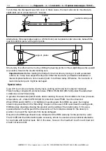
Preparation work for mounting

When using EPO3, C16/EPU or C16/ZOU44 to introduce and carry off the load, the following

preparations have to be made: A dowel pin is enclosed in the packing for every load cell with a max.

nominal load of 100t. This dowel pin and the rotation stop welded onto the load cell prevent a potential

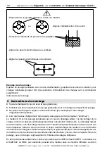
transducer microrotation, thus preventing the cable from being damaged. Use a hammer to drive in

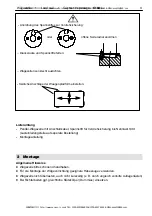
the dowel pin until it rests in the load introduction part’s pocket bore. Radially position the open side

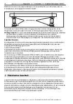
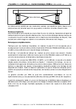
of the dowel pin (see illustration on page 11). The bore depth ensures correct fitting of the pin. Only

one load introduction part per load cell must be equipped with this pin. This load introduction part

must be mounted below the load cell to enable the dowel pin to engage into the rotation stop recess.

(Refer to the chapter on dimensions). No pin must be introduced into the bore on the upper load

introduction part.
Please refer to and comply with the special notes at the end of this chapter.

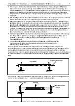
The areas or foundations below the lower load introduction part (for carrying off the load) and above

the upper load introduction part should be as even and level as possible. With areas complying with

these quality requirements, it is also possible to install or screw--fasten the load introduction parts

directly onto concrete so that no additional plates are needed.
Practically drill the required borings for securing and fixing on the weighing bridge and base plate

before you mount the weighing platform. The dimensions for the EPO, C16/EPU or C16/ZOU can

be found in the dimensioned drawings in chapter 5.

SUNSTAR传感与控制 http://www.sensor-ic.com/ TEL:0755-83376549 FAX:0755-83376182 E-MAIL:szss20@163.com

SUNSTAR自动化 http://www.sensor-ic.com/ TEL: 0755-83376489 FAX:0755-83376182 E-MAIL:szss20@163.com

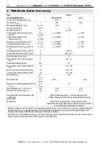
Summary of Contents for C16A Series

Page 1: ...Capteur de pesage Montageanleitung Installation instructions Instructions de montage C16A SUNSTAR http www sensor ic com TEL 0755 83376549 FAX 0755 83376182 E MAIL szss20 163 com SUNSTAR http www sens...
Page 2: ...ei Bruch Menschen und Sachen zu Schaden kommen k nnen m ssen vom Anwender entsprechende Sicherheitsma nahmen z B Absturzsicherungen getroffen werden einschl gige Unfallverh tungsvorschriften beachten...

Page 3: ...100t Lasteinleitungsteile auf seperate Bestellung Montageanleitung 2 Montage Allgemeine Hinweise D W gezelle bitte schonend handhaben D F r die Montage der W gevorrichtung geeignete Hebezeuge verwende...

Page 4: ...t cken Dieses mu unterhalb der W gezelle montiert werden da der Spannstift dann in die vorhandene Aussparung der Verdrehsicherung eingreifen kann siehe Kapitel Abmessungen Die Bohrung am oberen Drucks...

Page 5: ...ke absenken und an der anderen Stirnseite analog verfahren D Nach dem gesamten Einbau nochmals bei frei schwingender Br cke die lotrechte Einbaulage aller W gezellen kontrollieren und ggf bei angehobe...

Page 6: ...nutzt werden wie unter dem Kapitel Montage beschrieben Falls kundenseitig hergestellte Einbauteile verwendet werden stellt HBM Zeichnungen bereit die Lage und Montage der Verdrehsicherung zeigen Hierb...

Page 7: ...beln insbesondere zu Starkstrom und Steuerleitungen Falls dies nicht m glich ist sch tzen Sie die Me kabel z B durch Stahlpanzerrohre D Meiden Sie Streufelder von Trafos Motoren und Sch tzen 3 1 Paral...

Page 8: ...Umkehrspanne dhy 2 v CN 0 03302 0 0170 Linearit tsabweichung dlin 2 v CN 0 03002 0 01802 Belastungskriechen dDR ber 30min v CN 0 0330 0 0167 Eingangswiderstand RLC sw bl 700 20 Ausgangswiderstand R0 1...

Page 9: ...ruchung Fsrel Schwingbreite nach DIN 50 100 v Emax 70 Nennlast Emax t 20 30 40 60 100 20 30 40 60 100 Nennme weg ca 15 snom mm 0 65 0 75 0 85 1 22 1 57 0 65 0 75 0 85 1 22 1 57 Gewicht G mit Kabel ca...

Page 10: ...ruchlast Ed v Emax 350 200 Relative zul Schwingbeanspruchung Fsrel v Emax 70 Nennme weg ca 15 snom mm 1 57 2 15 Gewicht G mit Kabel ca kg 8 0 9 0 Schutzart IP nach EN 60529 IEC 529 und DIN 40 050 IP68...

Page 11: ...the user observe the relevant accident protection regulations Take into account the maximum limit loads given in the technical data The technical data for the load cells applies within the specified...

Page 12: ...roduce and carry off the load the following preparations have to be made A dowel pin is enclosed in the packing for every load cell with a max nominal load of 100t This dowel pin and the rotation stop...

Page 13: ...e is just no load on the load cells and that they can be aligned perpendicularly At the same time introduce the load cells upper load introduction parts into the upper load carrying element For this p...

Page 14: ...with protection class IP68 to EN 60 529 IEC 529 under the stated test conditions see technical data In general the load cells permit wash down cleaning However the conditions for max pressure temperat...

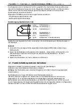
Page 15: ...en are the cause for the introduction of disturbing voltages into the measuring circuit Therefore D Use screened low capacitance cable only HBM cables meet these requirements D Do not lay the measurin...

Page 16: ...140 0 0116 0 0234 Hysteresis error dhy 2 of Emax 0 03302 0 0170 Non linearity dlin 2 of Emax 0 03002 0 01802 Creep dDR in 30 min of Emax 0 0330 0 0167 Input resistance RLC black blue 700 20 Output res...

Page 17: ...f Emax 350 Permissible dynamic load Fsrel vibration amplitude to DIN 50 100 of Emax 70 Max capacity Emax t 20 30 40 60 100 20 30 40 60 100 Deflection at max capacity approx 15 snom mm 0 65 0 75 0 85 1...

Page 18: ...rel vibration amplitude to DIN 50 100 of Emax 70 Weight G with cable approx Nominal deflection approx 15 snom kg lbs mm 8 0 17 5 1 57 9 0 19 7 2 15 Protection class IP to EN 60529 IEC 529 and DIN 40 0...

Page 19: ...par les r gles dispositions et normes aff rentes prescriptions sur la S curit du Travail et la Pr vention d Accidents doivent tre prises et appliqu es par l utilisateur lui m me telles que s curit s...

Page 20: ...e appel des appuis de m me hauteur dummies Le mod le C16 est un pesage pendulaire qui en cas de d calage lat ral de d centrage de la charge ram ne la bascule automatiquement dans une position initiale...

Page 21: ...our la fixation doivent tre r alis s avant le montage du pont sur le fondement Les cotes correspondantes en fonction des accessoires utilis s EPO C16 EPU ou C16 ZOU sont redonn es par les dessins cot...

Page 22: ...align s absolument la verticale faire alors pivoter les rondelles excentriques contre la pi ce d applique puis les arr ter au moyen des boulons de fixation aff rents En pr sence de grands carts de por...

Page 23: ...ves l IP 69K en ce qui concerne les pressions et temp ratures maximales respecter A l utilisation des accessoires HBM EPO3 C16 EPU ou C16 ZOU44 la s curit anti rotation int gr e pourra tre utilis e co...

Page 24: ...re Blindage du c ble sur la masse du bo tier Des champs lectriques et magn tiques sont souvent la cause de tensions parasites sur les circuits de mesure Pour cette raison veiller D n utiliser que des...

Page 25: ...y 2 de CN 0 03302 0 0170 Ecart de lin arit dlin 2 de CN 0 03002 0 01802 Fuite superficielle dDR sur 30min de CN 0 0330 0 0167 R sistance en entr e RLC sw bl 700 20 R sistance en sortie R0 1 rt ws 706...

Page 26: ...inte dynamique admise Fsrel Largeur d impulsions selon DIN 50100 de Emax 70 Charge nominale Emax t 20 30 40 60 100 20 30 40 60 100 Course nominale de mesure env 15 snom mm 0 65 0 75 0 85 1 22 1 57 0 6...

Page 27: ...e Fsrel Largeur d impulsions selon DIN 50100 de Emax 70 Course nominale de mesure env 15 snom mm 1 57 2 15 Poids approx G avec c ble kg 8 0 9 0 Indice de protection IP selon EN 60529 CEI 529 et DIN 40...

Page 28: ...R C16A 20t C16 ZOU44 200 150 123 130 5 13 6 4 0 49 C16A 30t C16 ZOU44 200 150 123 160 5 13 9 9 0 76 C16A 40t C16 ZOU44 200 150 123 180 5 13 12 2 0 94 C16A 60t C16 ZOU44 260 210 157 220 3 11 5 7 0 52...

Page 29: ...47 130 5 13 6 4 0 49 30t EPO3 C16 229 150 123 44 76 1 18 89 120 147 160 5 13 9 9 0 76 40t EPO3 50t C16 EPU44 229 150 123 44 76 1 18 89 120 147 180 5 13 12 2 0 94 60t 289 210 157 44 76 1 18 89 120 147...

Page 30: ...thalten Rotation stop bolt stainless steel included in scope of supply Goupille anti rotation livr e avec le peson 4xM16 147 90 120 EPO3 100t 18 10 EEK 6 3xM16 120 120 Ansicht von oben View from above...

Page 31: ...3 a max zul Schiefstellung in D max perm inclination in D Oblicit maxi admise en smax max zul seitliche Verschiebung der Lasteinleitung D max permissible lateral displacement of load introduction D d...

Page 32: ...t for max capacities up to 60t incl mounting set 2 9290 0070 3 excentric washers 90mm flexible tube tube clip EPO3 100t pendle support upper part for max capacity 100t incl spanner C16 EPU64 pendle su...

Reviews: