Interfaces
14
A03924_02_YI0_00
HBM: public
FIT
®
7A
6
Interfaces
The load cell can be provided with an RS‐485 interface, a CANopen interface,
or a DeviceNet interface, as required. The reference potential of all the
interface signals is GND (supply ground) of device socket 1.
6.1
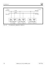
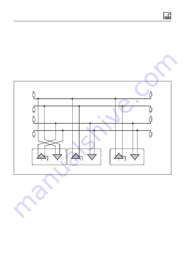
Connection of several load cells to a PC via RS-485
Line termination
Line termination
TB
TA
RB
RA
PC = Master
FIT7A_1 = Slave 01
FIT7A_89 = Slave 89
...
500
Ω
500
Ω
500
Ω
500
Ω
500
Ω
500
Ω
500
Ω
500
Ω
+5 V
+5 V
+5 V
+5 V
TxD on/off RxD
TB
TA
T
R
RB
RA
TxD on/off RxD
TB
TA
T
R
RB
RA
TxD on/off RxD
TB
TA
T
R
RB
RA
Fig. 6.1
Bus connection via RS‐485
Up to 89 load cells can be connected via the RS‐485 interface to a common
bus line, the total length of which can be as much as 500 m. Bus cabling for
4wire mode is shown in
.
Remember that many PCs do not have an RS‐485 interface. In this case, you
need an interface converter, such as the HBM converter (
).


