Inputs and outputs
FIT
®
7A
A03924_02_YI0_00
HBM: public
17
7
Inputs and outputs
7.1
Inputs
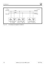
Apply the control signals between the particular input and reference potential
(GND). In the standard version, the trigger input can be directly activated with
a logic signal (HCMOS), although voltages up to 12V are also possible. The
inputs of device socket 2 are suitable for the signals of a PLC. The reference
potential in both cases is GND of device socket 1. The table below shows the
allocation of logic states to the voltage values at the input. Levels between the
stated high and low levels produce undefined states!
Trigger input
Inputs IN1, IN2
Reference potential
GND
GND
High level
>4V
>10V
Low level
<1V
<6V
Input resistance
70k
Ω
9k
Ω
Function
External trigger
TAR, Break, RUN functions
Quiescent level
Low level
Triggering event
Transition from high to low
level
1)
Stable level at trigger input used. The other wire must be at low level or not connected.
2)
Debouncing is dependent on the function set (IMD command), but not on the input used (device
socket 1 or 2).
7.2
Outputs
The output driver of the switch outputs is a PLC-compatible static switch
(High-Side driver). Power for switching must be supplied via external operating
voltage U
B2
. All the voltages apply to GND at device socket 1.
When an output is activated, a positive level is given on the corresponding
output line, voltage is dependent on U
B2
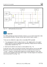
. The connected consumer is between
the output and the GND potential of the switching load supply:


