Interfaces
FIT
®
7A
A03924_02_YI0_00
HBM: public
15
6.2
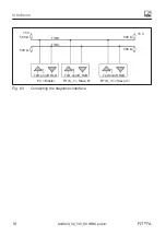
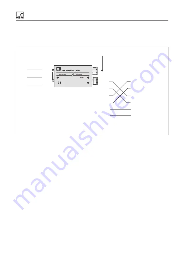
Connection to a PC with an RS‐232 interface via the
HBM interface converter
RS‐232
8...30V
2/4-wire
RS‐485
TxD
RxD
GND
RxD
TxD
GND
Interface converter
RS‐232 - RS‐485
PC COM port
D-Sub plug, 9-pin
(PC)
PIN
2 = RxD
3 = TxD
5 = GND
U
B
: 10
…
30V
DC
RS‐485 bus
TA
TB
RA
RB
GND
Uv
TA (blue)
TB (black)
RA (green)
RB (gray)
GND
U
v
(red, 10 ... 30V
DC
)
(white)
Equivalent designations:
TA = T-
RA = R-
TB = T+
RB = R+
D-Sub socket, 9-pin
(converter)
PIN
2 = TxD
3 = RxD
5 = GND
FIT7A
Fig. 6.2
Connection to a PC via the HBM interface converter
6.3
Connection to a CANopen interface
The interface is set up using the CANopen standard DS301. The load cell
address on delivery is 63.
6.4
Connection to a DeviceNet interface
The interface is set up using the DeviceNet specification, Release 2.0 ODVA.
The load cell address on delivery is 63.
6.5
Diagnostic interface connection
The real time values stored with the diagnostic function can be read out via this
interface. The load cell address on delivery is 31, the baud rate is fixed at
38600Bd.


