Analog to Digital Conversion
Sample rate per channel
0.1 S/s to 1 MS/s
ADC resolution; one ADC per channel
16 bit
ADC Type
Successive Approximation Register (SAR); TI ADS8401IB
Time base accuracy
Defined by mainframe:
±
3.5 ppm
(1)
; aging after 10 years
±
10 ppm
Binary sample rate
Supported; when calculating FFTs results in rounded/integer BIN sizes
Maximum binary sample rate
1.024 MS/s
External time base sample rate
0 S/s to 500 kS/s
External time base level
TTL
External time base minimum pulse width
200 ns
(1)
Mainframes using Interface/Controller modules shipped before 2012:
±
30 ppm
Anti
-
Alias Filters
Using different filter selections (Wideband/Bessel IIR/FIR/etc.) or different filter bandwidths can result in phase mismatches between channels.
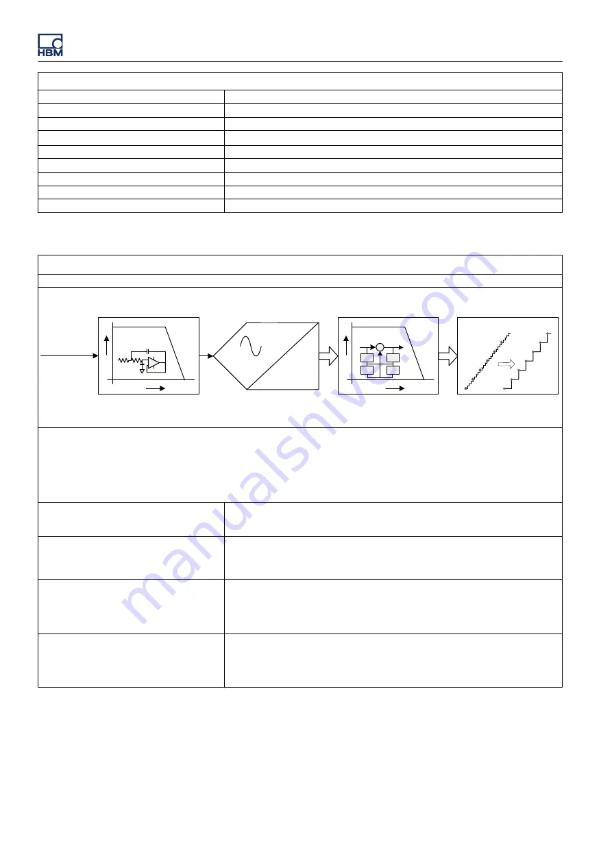
SAR ADC
Sample Rate Selection
Analog Input
Digital Filter (Anti-Alias)
1 out of N
A
F
Analog Anti-Alias Filter
1010
A
F
y
(n)
n
-1
n
-1
Σ
x
(n)
z
-1
z
-1
Figure L.19:
Combined analog and digital anti
-
alias filter block diagram
Anti
-
aliasing is prevented by a steep, fixed frequency analog anti
-
alias filter in front of the Analog to Digital Converter (ADC). The ADC always
samples at a fixed sample rate. The fixed sample rate of the ADC avoids the need for different analog anti
-
alias filter frequencies.
Directly behind the ADC, the high precision digital filter is used as anti
-
alias protection before the digital downsampling to the desired user
sample rate is performed. The digital filter is programmed to a fraction of the user sample rate and automatically tracks any user sample rate
selection. Compared to analog anti
-
alias filters, the programmable digital filter offers additional benefits like higher order filter with steep roll
-
off, a larger selection of filter characteristics, noise
-
free digital output and no additional phase shifts between channels that use the same filter
settings.
Wideband
When wideband is selected, there is neither an analog anti
-
alias filter nor any digital filter
in the signal path. Therefore, there is no anti
-
alias protection when wideband is selected.
Should not be used if working in a frequency domain with recorded data.
Digital Bessel IIR (Fc @
-
3 dB)
When Bessel IIR filter is selected, this is always a combination of an analog Bessel anti
-
alias filter and a digital Bessel IIR filter to prevent aliasing at lower sample rates.
Bessel filters are typically used when looking at signals in the time domain. Best used for
measuring transient signals or sharp edge signals like square waves or step responses.
Digital FIR (Fc @
-
0.1 dB)
Standard FIR filter with corner frequency (Fc) defined at
-
0.1 dB.
When FIR filter is selected, this is always a combination of an analog Butterworth anti
-
alias
filter and a digital FIR filter to prevent aliasing at lower sample rates.
This filter is best used when working in the frequency domain. When working in the time
domain, this filter is best used for signals that are (close to) sine waves.
Digital FIR (Fc @
-
3 dB)
Supported by Perception V6.40 and higher
Adapted FIR filter with corner frequency (Fc) calculated as close as possible to
-
3 dB.
When FIR filter is selected, this is always a combination of an analog Butterworth anti
-
alias
filter and a digital FIR filter to prevent aliasing at lower sample rates.
This filter is best used when working in the frequency domain. When working in the time
domain, this filter is best used for signals that are (close to) sine waves.
GEN3i
1054
I3763-3.1 en HBM: public


