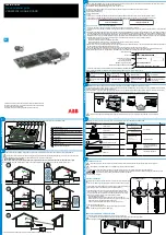
Resistive Temperature Detectors (RTD) mode and cabling
Sense (-)
TEDS
Control
Teds (+)
Teds (-)
TEDS class 2/3
Amplifier
-1
Excitation
Excitation (-)
Sense (+)
Excitation (+)
Signal (-)
Signal (+)
Signal ground
+
-
+V
-V
Signal conditioner
+
-
+
-
U
excit
350 Ω
-
¼ bridge
TEDS
Class 2
optional
RTD
TEDS Class 3
10 MΩ
10 MΩ
Pt10
Pt100
Pt500
Pt1000
Pt2000
Figure 12.57:
RTD mode block diagram
10
2
3
4
5
6
7
8
9
11
14
13
12
1
RTD / Pt1000
KAB4-3133.0002
GN1640B
GN840B
350 Ω
-
¼ bridge
Sense
Excitation
Sense
Excitation
(+)
(+)
Signal ground
RTD
White
Red
Shield
Green
Connect
Keep wire length < 5 cm
Blue
Earth shield
12
2
11
1
4
10
Housing
Signal
(-)
(-)
8
LS 2
Shield
GEN3i
I3763-3.1 en HBM: public
283


