Analog Input Section
Channels
4
Connectors
2 isolated (plastic) BNCs per channel
Input type
Analog, isolated balanced differential
Input impedance
2 * 1 MΩ
±
1% // 100 pF
±
10%
Input coupling
Coupling modes
Current, AC, DC, GND
AC coupling frequency
0.16 Hz,
±
10%;
-
3 dB
-60
-50
-40
-30
-20
-10
0
0.0001
0.001
0.01
0.1
1
10
M
ag
n
it
u
d
e
[d
B
]
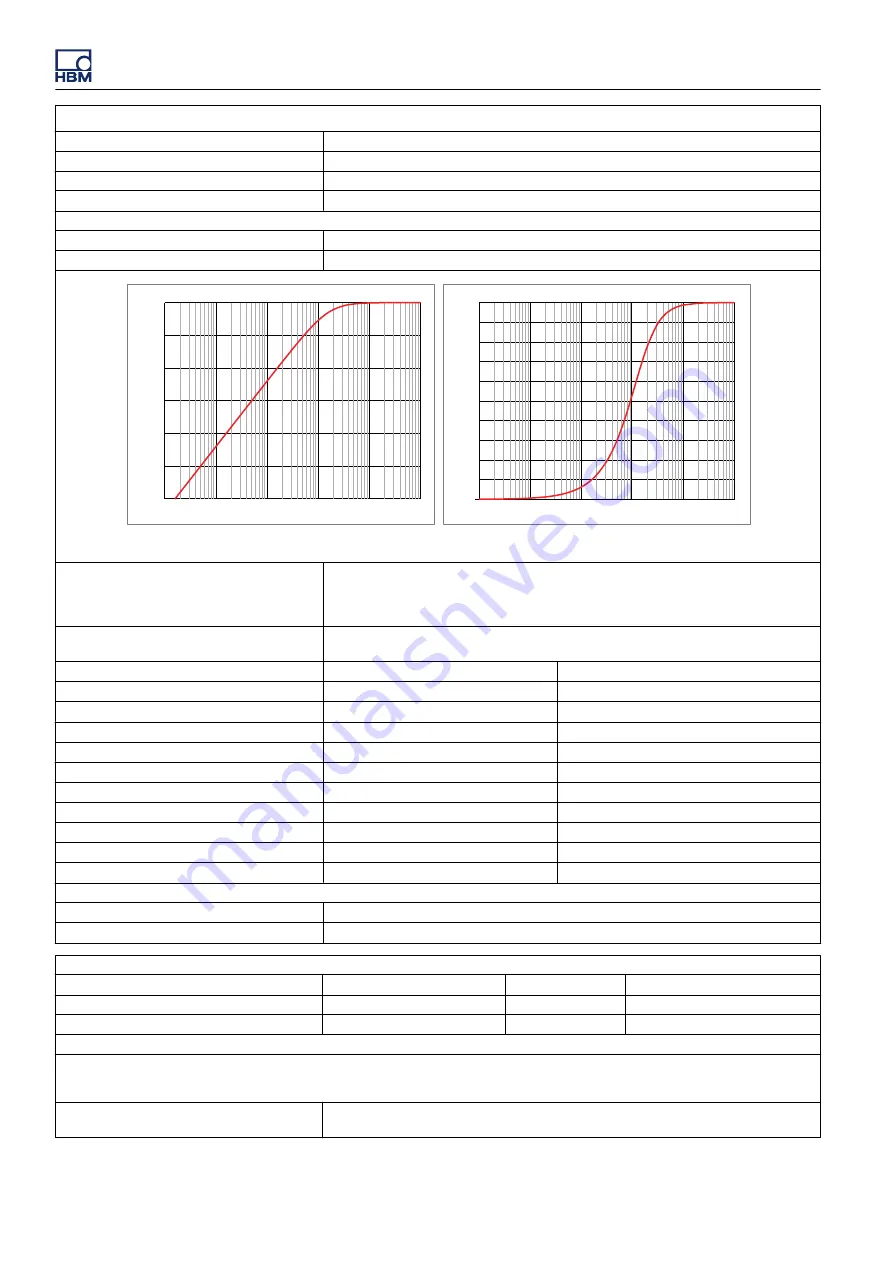
0.16 Hz AC coupling response [dB]
0
10
20
30
40
50
60
70
80
90
100
0.0001
0.0010
0.0100
0.1000
1.0000
10.0000
M
ag
n
it
u
d
e
[%
]
Frequency [Hz]
0.16 Hz AC coupling response [%]
Frequency [Hz]
Figure A.69:
Representative AC coupling response
Ranges
±
10 mV,
±
20 mV,
±
50 mV,
±
0.1 V,
±
0.2 V,
±
0.5 V,
±
1.0 V,
±
2.0 V,
±
5.0 V,
±
10.0 V,
±
20.0 V,
±
50.0 V,
±
100.0 V
Each range supports a variable gain in 1000 steps (0.1%). This creates 1000 extra ranges
between 2 specified ranges
Offset
±
50% in 1000 steps (0.1%)
±
100 V range has fixed 50% offset
DC Offset error
Voltage
Current
Wideband
0.1% of Full Scale
±
600 μV
0.175% of Full Scale
±
825 μV
Bessel IIR and FIR
0.1% of Full Scale
±
100 μV
0.200% of Full Scale
±
300 μV
Offset error drift
±
120 ppm/°C (
±
216 ppm/°F)
±
120 ppm/°C (
±
216 ppm/°F)
DC Gain error
Voltage
Current
Wideband
0.1% of Full Scale
±
100 μV
0.2% of Full Scale
±
300 μV
Bessel IIR and FIR
0.1% of Full Scale
±
100 μV
0.2% of Full Scale
±
300 μV
Gain error drift
±
70 ppm/°C (
±
126 ppm/°F)
±
70 ppm/°C (
±
126 ppm/°F)
Maximum static error (MSE)
Voltage
Current
Wideband
0.1% of Full Scale
±
600 μV
0.165% of Full Scale
±
1035 μV
Bessel IIR and FIR
0.1% of Full Scale
±
100 μV
0.200% of Full Scale
±
300 μV
RMS Noise
Wideband
0.02% of Full Scale
±
116 μV
Bessel IIR and FIR
0.02% of Full Scale
±
116 μV
Common mode (referred to system ground)
Ranges
Less than or equal to
±
1 V
±
2 V to
±
10 V
Larger than or equal to
±
20 V
Rejection (CMR)
> 72 dB
> 72 dB
> 72 dB
Maximum common mode voltage
4 V DC
40 V DC
250 V DC
Input overload protection
Overvoltage impedance change the activation of the overvoltage protection system results in a reduced input impedance.
The overvoltage protection is not active for as long as the input voltage remains less than 200% of the selected input range or 250 V, whichever
value is the smallest.
Maximum nondestructive voltage
±
100 V DC; Ranges ≤
±
1 V
±
250 V DC; Ranges >
±
1 V
GEN3i
468
I3763-3.1 en HBM: public


