11
ME 30
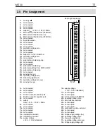
2.5
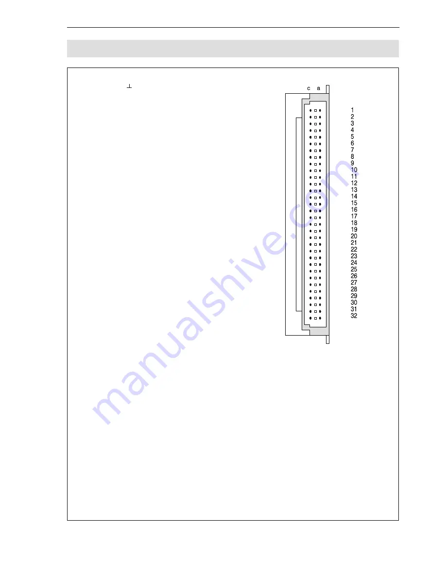
Pin Assignment
64-pin right angle plug
1c
housing
2c
not occupied
3c
not occupied
4c
not occupied
5c
not occupied
6c
output U
add.
=+14.5...+15.5V; <50mA
7c
MR1 external fine balance (R=5kOhm)
8c
MR1 external fine balance. tap
9c
MR1 external fine balance (R=5kOhm)
10c not occupied
11c Synchronization
12c not occupied
13c not occupied
14c not occupied
15c operating voltage zero
16c not occupied
17c not occupied
18c output U
A
=
±
10V; R>5kOhm
19c operating voltage zero
20c not occupied
21c external zero balancing tap
22c not occupied
23c not occupied
24c external zero balancing
25c external switching from MR1 to MR2
26c external zero balancing
27c not occupied
28c sensing line (gn)
29c operating voltage zero
30c measuring signal (wh)
31c operating voltage zero (ye)
32c sensing line (gy)
St 21
1a
not occupied
2a
not occupied
3a
not occupied
4a
DC-DC converter positive pole
5a
DC-DC converter negative pole
6a
not occupied
7a
output
U
add.
=–14.5...–15.5V; <50mA
8a
not occupied
9a
not occupied
10a not occupied
11a not occupied
12a not occupied
13a internally connected
14a internally connected
15a supply voltage
+14.5...+15.5V (standard)
16a supply voltage
–14.5...–15.5V (standard)
17a not occupied
18a not occupied
19a current output with EM002
20a operating voltage zero
21a zero function, external
22a not occupied
23a not occupied
24a not occupied
25a calibration function, external
26a not occupied
27a not occupied
28a bridge supply voltage (bu)
29a operating voltage zero
30a measuring signal (rd)
31a operating voltage zero (ye)
32a bridge supply voltage (bl)
Summary of Contents for ME30
Page 2: ......
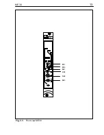
Page 13: ...13 ME 30 P21 P22 ME30 S21 P23 S22 S23 Fig 3 1 Front view ME30 ...
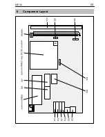
Page 23: ...23 ME 30 8 Component Layout ...
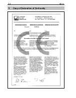
Page 24: ...24 ME 30 9 Copy of Declaration of Conformity ...
Page 25: ...25 ME 30 ...
Page 26: ...26 ME 30 ...
Page 27: ...27 ME 30 ...


