14
ME 30
4
Individual Settings
Various ex-works settings on the measuring amplifier card can be altered.
Adaptations, which are of no problem, can be carried out by means of the DIP
switch on the board or also by externally wired switching elements. If re-
quested with the order, they can be carried out by the manufacturer.
4.1
Operational Setting
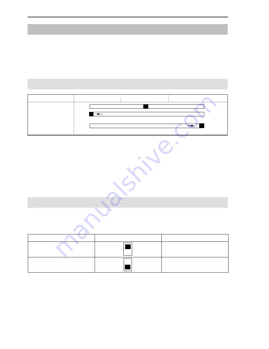
Zero
Measure
Calibrate
S21
or connect pin 21a to pin 15c
or connect pin 25a to pin 15c
Switch
The transducer signal is switched off in the ”Zero” function, so that the ”Zero
Value” of the amplifier is applied to the output. This function enables amplifiers
to be replaced in measuring chain without the need for rebalancing the bridge
with the unloaded transducer. All that is required is that the amplifier balance
values are noted and then this value is set, if necessary, with P23, S22 and
S23.
4.2
Setting the Measuring Range
Measuring range 1 is get ex-works. Measuring range 2 can be activated by
switching DIP switch S24/4 or by external switching.
Measuring Range
S 24/4
Externally
MR 1 =
±
2mV/V
(ex-works setting)
–
MR 2 =
±
0.2mV/V
from MR1 to MR2;
connect 25c and 15c
Any alteration to the measuring ranges between
±
0.2mV/V and
±
4mV/V with
U
B
= 5V (resp.
±
0.4mV/V and
±
8mV/V with U
B
= 2.5V) can be made by
means of the DIP switches S26 and S27. For fine balancing see 3.3.
Summary of Contents for ME30
Page 2: ......
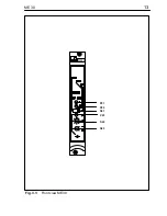
Page 13: ...13 ME 30 P21 P22 ME30 S21 P23 S22 S23 Fig 3 1 Front view ME30 ...
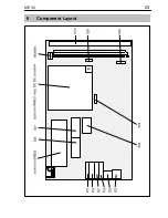
Page 23: ...23 ME 30 8 Component Layout ...
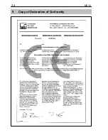
Page 24: ...24 ME 30 9 Copy of Declaration of Conformity ...
Page 25: ...25 ME 30 ...
Page 26: ...26 ME 30 ...
Page 27: ...27 ME 30 ...


