11
P3
…
/P3 Top Class
A2239-3.0 en/de/fr
HBM
4
Installation
The pressure transducer can be screwed in wherever required. If the
transducer is used to measure dynamic pressure characteristics in liquids, it
should be installed with the pressure connection pointing upward, so that it is
not possible for an air cushion to build up in the measurement tube.
The connecting pin with the M 12 x 1.5 and M 20 x 1.5 threaded connectors for
the P3/3000 bar type, corresponds to DIN 16288.
CAUTION:
When tightening, the wrench (27 a.f.) must only be put to the flat of the
mounting flange and not to the housing or to the cable entry. The
permissible tightening torque is 30 N
V
m.
Pay particular attention to the sealing on the thread of the connecting pin. The
pressure medium and the respective conditions of installation for the individual
case will determine which type of sealing is suitable. Some of the sealing
options are shown below.
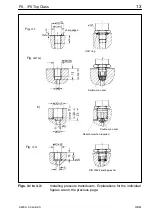
Fig. 4.1:
The USIT ring U 12.7 x 20 x 1.5 belongs to the accessories
supplied with the P3 transducer up to 500 bar full scale value. For a
perfect seal, the bearing surfaces must be mostly flat and without
marks. The pin hole must not have spot‐facing and should only be
slightly deburred, as the pressure of the measurement medium
pushes the lips of the seal against the transducer and the bearing
surface.
Fig. 4.2:
The transducers with the 500 to 3000 bar full scale value come
supplied with a double‐cone seal made of rustproof, acid‐proof
steel, material no. 1.4305. This makes a perfect seal, even at high
static and dynamic pressures.
a) P3/ 500 bar to P3/ 2000 bar
Connection hole and seal installation.
b) P3/ 3000 bar
Connection hole with relief bore and seal installation.
Fig. 4.3:
With this seal with sealing washers per DIN 16258, only washers
made of non‐metallic materials should be used. If relevant metallic
washers are used, the surface pressure required for a perfect seal


