background image

PWSE

6

A3361-1.0 en/de/fr

HBM

Maintenance

The PWSE load cells are maintenance free.

Selling on

If the load cell is sold on, these mounting instructions must be included with
the load cell.

Environmental protection, disposal

In accordance with national and local environmental protection and material
recovery and recycling regulations, old transducers that can no longer be
used must be disposed of separately and not with normal household waste.

If you need more information about waste disposal, please contact your local
authorities or the dealer from whom you purchased the product.

Qualified personnel

Qualified personnel means persons entrusted with siting, mounting, starting
up and operating the product, who possess the appropriate qualifications for
their function.

This includes people who meet at least one of the three following require­
ments:

- Knowledge of the safety concepts of automation technology is a require­

ment and as project personnel, you must be familiar with these concepts.

- As automation plant operating personnel, you have been instructed how to

handle the machinery. You are familiar with the operation of the equipment
and technologies described in this documentation.

- As commissioning engineers or service engineers, you have successfully

completed the training to qualify you to repair the automation systems. You
are also authorized to activate, ground and label circuits and equipment in
accordance with safety engineering standards.

Summary of Contents for PWSE

Page 1: ...A3361 1 0 en de fr Single point load cells Plattformw gezellen Pesons plateforme PWSE Mounting Instructions Montageanleitung Notice de montage...

Page 2: ...English Page 3 13 Deutsch Seite 14 24 Fran ais Page 25 32...

Page 3: ...n site 8 2 1 Protection against corrosion 8 2 2 Deposits 8 3 Mechanical installation 9 3 1 Important precautions during installation 9 3 2 Mounting 9 4 Electrical connection 11 4 1 Connection with six...

Page 4: ...limits The data in the technical data sheet must be complied with when using the load cells In particular the respective maximum loads specified must never be exceeded The following limits set out in...

Page 5: ...use of the load cells or by non compliance with the mounting and operating instructions these safety instructions or any other applicable safety regulations BG safety and accident prevention regulatio...

Page 6: ...s persons entrusted with siting mounting starting up and operating the product who possess the appropriate qualifications for their function This includes people who meet at least one of the three fol...

Page 7: ...low warns of a potentially dangerous situation in which failure to comply with safety requirements can result in death or serious physical injury WARNING Description of a potentially dangerous situati...

Page 8: ...r the cable NOTE Acids and all substances that release ions also attack stainless steels and their welded seams Should there be any corrosion this could cause the transducer to fail In this case appro...

Page 9: ...nnel of the system in which the transducer is installed Implement appropriate safety measures to avoid overloads or to protect against resulting dangers NOTE Load cells are precision measuring element...

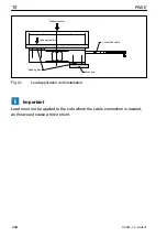
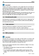
Page 10: ...latform center Load application Connection cable Mounting Spacing disc Fig 3 1 Load application and installation Important Load must not be applied to the side where the cable connection is located as...

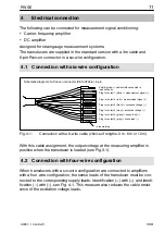
Page 11: ...n sense lead Plug in contact 2 red measurement signal Schematic diagram of a Pancon connector CE100F26 6 6 pin 1 2 3 5 6 blue marking Shield yellow cable shield connected to load cell body Fig 4 1 Con...

Page 12: ...without adversely affecting the measurement accuracy 4 4 Cable extension Only use shielded low capacitance measurement cables for extension Ensure that connection is perfect with a low contact resist...

Page 13: ...und the transducer amplifier and indicator more than once Connect all devices in the measurement chain to the same grounded conductor The best EMC protection is ensured with an arrangement where the l...

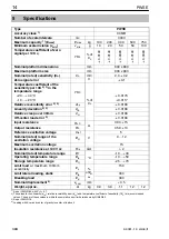
Page 14: ...Off center load error 3 0 0166 Input resistance RLC 390 15 Output resistance R0 359 10 Reference excitation voltage Uref V 5 Nominal rated range of the excitation voltage BU 0 12 Maximum excitation vo...

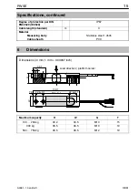
Page 15: ...gth standard m 3 Material Measuring body Cable sheath Stainless steel 1 4545 PVC 6 Dimensions Dimensions in mm 1 mm 0 03937 inch H 38 1 G T W 7 8 22 4 0 1 79 3 0 1 22 4 0 1 139 7 Load direction platfo...

Page 16: ...PWSE 16 A3361 1 0 en de fr HBM...

Page 17: ...e Kennzeichnungen 21 2 Bedingungen am Einbauort 22 2 1 Korrosionsschutz 22 2 2 Ablagerungen 22 3 Mechanischer Einbau 23 3 1 Wichtige Vorkehrungen beim Einbau 23 3 2 Montage 23 4 Elektrischer Anschluss...

Page 18: ...zellen setzt sachgem en Transport fachgerechte Lagerung Aufstellung und Montage sowie sorgf ltige Bedienung voraus Belastbarkeitsgrenzen Beim Einsatz der W gezellen sind die Angaben in den technischen...

Page 19: ...Aufnehmern k nnen Gefahren ausgehen wenn sie von unge schultem Personal oder unsachgem montiert aufgestellt eingesetzt und bedient werden Jede Person die mit Aufstellung Inbetriebnahme Betrieb oder Re...

Page 20: ...ll zu entsorgen Falls Sie weitere Informationen zur Entsorgung ben tigen wenden Sie sich bitte an die rtlichen Beh rden oder an den H ndler bei dem Sie das Produkt erworben haben Qualifiziertes Perso...

Page 21: ...nung weist auf eine m gliche gef hrliche Situation hin die wenn die Sicherheitsbestimmungen nicht beachtet werden Tod oder schwere K rperverletzung zur Folge haben kann WARNUNG Beschreibung einer m gl...

Page 22: ...bel angreifen HINWEIS S uren und alle Stoffe die Ionen freisetzen greifen auch nichtrostende St hle und deren Schwei n hte an Die dadurch auftretende Korrosion kann zum Ausfall des Aufnehmers f hren S...

Page 23: ...er Aufnehmer eingebaut ist Treffen Sie geeignete Sicherungsma nahmen zur Vermeidung einer berlas tung oder zur Sicherung gegen sich daraus ergebende Gefahren HINWEIS W gezellen sind Pr zisions Messele...

Page 24: ...Plattform Lasteinleitung Anschlusskabel Befestigung Distanzscheibe Abb 3 1 Lasteinleitung und Einbau Wichtig Die Lasteinleitung darf nicht auf der Seite des Kabelanschlusses erfolgen dies f hrt zu ein...

Page 25: ...g Steckkontakt 2 rot Messsignal Prinzipdarstellung des Pancon Steckers CE100F26 6 6 pol 1 2 3 5 6 blaue Markierung Schirm gelb Kabelschirm mit W gezellenk rper verbunden Abb 4 1 Anschluss mit 6 adrige...

Page 26: ...r Technik k nnen Sie das Kabel des Aufnehmers bei Bedarf k rzen ohne dass dadurch die Messgenauigkeit beeintr chtigt wird 4 4 Kabelverl ngerung Verwenden Sie nur abgeschirmte kapazit tsarme Messkabel...

Page 27: ...Meiden Sie Streufelder von Trafos Motoren und Sch tzen Erden Sie Aufnehmer Verst rker und Anzeigeger t nicht mehrfach Schlie en Sie alle Ger te der Messkette an den gleichen Schutzleiter an Einen herv...

Page 28: ...chen ber 30 min dcr 0 0166 Eckenlastfehler 7 0 0166 Eingangswiderstand RLC 390 15 Ausgangswiderstand R0 359 10 Referenzspeisespannung Uref V 5 Nennbereich der Speisespannung BU 0 12 Maximale Speisespa...

Page 29: ...e Standard m 3 Material Messk rper Kabelmantel Nichtrostender Stahl 1 4545 PVC 6 Abmessungen Abmessungen in mm 1 mm 0 03937 Zoll H 38 1 G T W 7 8 22 4 0 1 79 3 0 1 22 4 0 1 139 7 Belastungsrichtung Mi...

Page 30: ...PWSE 30 A3361 1 0 en de fr HBM...

Page 31: ...vironnantes respecter 37 2 1 Protection contre la corrosion 37 2 2 D p ts 37 3 Montage m canique 38 3 1 Pr cautions importantes lors du montage 38 3 2 Montage 38 4 Raccordement lectrique 40 4 1 Raccor...

Page 32: ...l convient de veiller un transport un stockage une installation et un montage appropri s et d assurer un maniement scrupuleux Limites de capacit de charge Lors de l utilisation des pesons respecter im...

Page 33: ...es g n raux en cas de non respect des consignes de s curit Les pesons correspondent au niveau de d veloppement technologique actuel et pr sentent une parfaite s curit de fonctionnement Les capteurs pe...

Page 34: ...n Cession En cas de cession du peson la pr sente notice de montage doit tre jointe au peson Protection de l environnement limination des d chets Conform ment aux r glementations nationales et locales...

Page 35: ...ervice ou de la maintenance vous disposez d une formation vous autorisant r parer les installations d automatisation Vous tes en outre autoris mettre en service mettre la terre et marquer des circuits...

Page 36: ...sque potentiel qui si les dispositions relatives la s curit ne sont pas respect es peut avoir pour cons quence de graves blessures corporelles voire la mort AVERTISSEMENT Description d une situation p...

Page 37: ...c ble NOTE Les acides et toutes les substances lib rant des ions attaquent galement les aciers inoxydables et leurs cordons de soudure La corrosion ventuelle qui peut en r sulter est susceptible d ent...

Page 38: ...des mesures de protection appropri es pour viter toute surcharge ou pour se prot ger des risques qui pourraient en d couler NOTE Les pesons sont des l ments sensibles de pr cision et doivent donc tre...

Page 39: ...de la plateforme Application de charge C ble de liaison Fixation Entretoise Fig 3 1 Application de charge et montage Important La charge ne doit pas tre appliqu e du c t du raccordement du c ble afin...

Page 40: ...l de contre r action Contact 2 rouge signal de mesure Sch ma de principe du connecteur Pancon CE100F266 6 p les 1 2 3 5 6 Marquage bleu Blindage jaune blindage de c ble reli au corps du peson Fig 4 1...

Page 41: ...ble Lors d un raccordement du capteur l amplificateur en technique six fils le c ble du capteur peut tre raccourci le cas ch ant sans nuire l exactitude de mesure 4 4 Rallonge de c ble Utiliser unique...

Page 42: ...n est pas possible prot ger le c ble de mesure par ex l aide de tubes d acier blind s viter les champs de dispersion des transformateurs moteurs et vannes ne pas mettre plusieurs fois la terre le capt...

Page 43: ...0 0166 R sistance d entr e RLC 390 15 R sistance de sortie R0 359 10 Tension d alimentation de r f rence Uref V 5 Plage nominale de tension d alimentation BU 0 12 Tension d alimentation maximale 15 R...

Page 44: ...le standard m 3 Mat riau l ment de mesure Gaine de c ble Acier inoxydable 1 4545 PVC 6 Dimensions Dimensions en mm 1 mm 0 03937 pouce H 38 1 F P L 7 8 22 4 0 1 79 3 0 1 22 4 0 1 139 7 Direction de cha...

Page 45: ...45 PWSE A3361 1 0 en de fr HBM...

Page 46: ...PWSE 46 A3361 1 0 en de fr HBM...

Page 47: ......

Page 48: ...are not to be understood as express warranty and do not constitute any liability whatsoever nderungen vorbehalten Alle Angaben beschreiben unsere Produkte in allgemeiner Form Sie stellen keine Bescha...

Reviews: