background image

Marquages utitlisés

8

A2447-1.1


HBM: public

SP4M

Symbole

Signification

ATTENTION

Ce marquage signale un risque 

potentiel

 qui -

si les dispositions relatives à la sécurité ne
sont pas respectées - 

peut avoir

 pour

conséquence des blessures corporelles de
gravité minime ou moyenne.

Note

Ce marquage signale une situation qui - si les
dispositions relatives à la sécurité ne sont pas
respectées - 

peut avoir

 pour conséquence des

dégâts matériels.

Mise en valeur
Voir …

Pour mettre en valeur certains mots du texte,
ces derniers sont écrits en italique.

Summary of Contents for SP4M Series

Page 1: ...Mounting Instructions Montageanleitung Notice de montage English Deutsch Fran ais SP4M...

Page 2: ...product descriptions are for general information only They are not to be understood as a guarantee of quality or durability nderungen vorbehalten Alle Angaben beschreiben unsere Produkte in allgemeine...

Page 3: ...Mounting Instructions Montageanleitung Notice de montage English Deutsch Fran ais SP4M...

Page 4: ...7 2 2 Markings used in this document 7 3 Mounting and Load application 9 4 Electrical connection 10 4 1 Connecting in four wire and six wire configurations 10 4 2 Shortening the cable 11 4 3 Cable ex...

Page 5: ...designed for metrological applications Use for any additional purpose shall be deemed to be not appropriate In the interests of safety load cells should only be oper ated as described in the Mounting...

Page 6: ...nt and respond to the safety engineering considerations of the weighing technology in such a way as to minimize remaining dangers Prevailing regulations must be complied with at all times Reference mu...

Page 7: ...erned The same applies to the use of accessories Qualified personnel means persons entrusted with siting mounting starting up and operating the product who possess the appropriate qualifications for t...

Page 8: ...talling this version it is essential to comply with the relevant installation regulations S There must be compliance with the installation condi tions cited in the Declaration of Conformity and or the...

Page 9: ...national and local environmental protection and material recovery and recycling regula tions old devices that can no longer be used must be disposed of separately and not with normal household garbag...

Page 10: ...to comply with safety requirements can result in slight or moderate physical injury Notice This marking draws your attention to a situation in which failure to comply with safety requirements can lea...

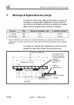
Page 11: ...1 36 kg M6 8 8 6 N m 50 200 kg M6 10 9 14 N m 1 Recommendedvalue for the stated property class For screw dimensioning please refer to the appropriate information given by the screw manufacturers Load...

Page 12: ...ion are connected to amplifiers with a four wire configuration the sense leads of the load cells must be connected to the corre sponding excitation leads 6 wire cable connection a choice of lengths 1...

Page 13: ...of the same type 4 4 Parallel connection option Only single point load cells with an aligned output nomi nal rated sensitivity and output resistance are suitable for parallel connection Many of HBM s...

Page 14: ...cell to gether with the connection cable and the subsequent electronics should be placed in a shielded housing Exception Load cells with shielded round cables are EMC tested in accordance with EC dire...

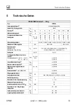
Page 15: ...rm size mm 300 300 450 450 Nominal sensitivity Maximum capacity 1 kg Maximum capacities 3 kg 200 kg Cn mV V 1 8 0 27 0 18 Option 6 A1 1 8 mV V 0 1 2 0 0 2 Option 6 A 2mV V 0 1 Zero signal mV V 0 0 1 T...

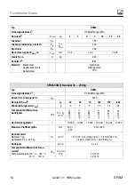
Page 16: ...r PVC SP4M C3MR Capacity 1 20 kg Type SP4M Accuracy class1 C3 Multi Range MR Number of load cell verification intervals nLC 3000 Maximum capacity2 Emax kg 30 50 75 100 150 200 Minimum load cell verifi...

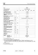
Page 17: ...GW 2 Nominal rated range of the ambient temperature BT C 10 40 Operating temperature range Btu 10 50 Storage temperature range Btl 25 70 Limit load EL of Emax 150 Limit lateral loading static Elq 300...

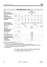
Page 18: ...sensitivity Cn mV V 2 0 0 2 1 8 0 18 2 0 0 2 2 4 0 24 Zero signal 0 0 10 Temperature coefficient of sensitivity3 Temperature range 20 40 C 10 20 C TCS of Cn 10 K 0 0087 0 0058 Relative reversibility e...

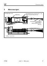
Page 19: ...cable 3000 50 mm Cable and plug see chapter 4 Electrical connection page 10 12345678 week year v 19 1 M6x0 5 16 deep M6x1 6H 34 35 39 25 4 19 1 99 6 19 1 6 1 150 Load direction SP4C3 MR 20kg SP4M 1 k...

Page 20: ...Dimensions 18 A2447 1 1 HBM public SP4M...

Page 21: ...Mounting Instructions Montageanleitung Notice de montage English Deutsch Fran ais SP4M...

Page 22: ...rachte Symbole 7 2 2 In dieser Anleitung verwendete Kennzeichnungen 7 3 Montage und Lasteinleitung 9 4 Elektrischer Anschluss 10 4 1 Anschluss in Vier und Sechsleiter Technik 10 4 2 Kabelk rzung 11 4...

Page 23: ...t Jeder dar ber hinausgehende Gebrauch gilt als nicht bestimmungsgem Zur Gew hrleistung eines sicheren Betriebes d rfen die W gezellen nur nach den Angaben in der Montageanlei tung verwendet werden Be...

Page 24: ...W getechnik sind zus tzlich vom Anlagenplaner Ausr ster Betreiber so zu planen zu reali sieren und zu verantworten dass Restgefahren minimiert werden Jeweils existierende Vorschriften sind zu beach te...

Page 25: ...tzen Hierbei sind zus tzlich die f r den jeweiligen Anwen dungsfall erforderlichen Rechts und Sicherheitsvorschrif ten zu beachten Sinngem gilt dies auch bei Verwen dung von Zubeh r Qualifiziertes Per...

Page 26: ...d rfen keine Kr fte und Momente ber den Federbereich geleitet werden Option Explosionsschutzausf hrung S Bei der Installation sind die einschl gigen Errichtungs bestimmungen unbedingt zu beachten S Di...

Page 27: ...ehr gebrauchsf hige Altger te sind gem den nationalen und rtlichen Vorschriften f r Umweltschutz und Rohstoffr ckgewinnung getrennt von regul rem Hausm ll zu entsorgen Falls Sie weitere Informationen...

Page 28: ...gen nicht beachtet werden leichte oder mittlere K rperverletzung zur Folge haben kann Hinweis Diese Kennzeichnung weist auf eine Situation hin die wenn die Sicherheitsbestimmungen nicht beachtet werde...

Page 29: ...asse Anzugsmoment1 1 36 kg M6 8 8 6 N m 50 200 kg M6 10 9 14 N m 1 Richtwert f r die angegebene Festigkeitsklasse Zur Auslegung von Schrauben beachten Sie bitte entsprechende Informationen der Schraub...

Page 30: ...er mit Vierleiter Technik angeschlossen werden sind die F hlerleitungen der W gezellen mit den entsprechenden Speiseleitungen zu verbinden Anschluss mit 6 adrigem Kabel L ngen w hlbar 1 5 m 3 m 6 m 12...

Page 31: ...er Sechsleiter W gezelle kann mit einem gleichartigen Kabel verl ngert werden 4 4 Parallelschaltung Option Nur Plattform W gezellen mit abgeglichenen Ausgang Nennkennwert und Ausgangswiderstand sind z...

Page 32: ...w hrleisten sollte die W gezelle mit dem Anschlusskabel und der nachfolgen den Elektronik gemeinsam in einem geschirmten Ge h use untergebracht sein Ausnahme W gezellen mit geschirmten Rundkabel sind...

Page 33: ...3 kg 200 kg Cn mV V 1 8 0 27 0 18 Option 6 A1 1 8 mV V 0 1 2 0 0 2 Option 6 A 2mV V 0 1 Nullsignal mV V 0 0 1 Temperaturkoeffizient des Kenn wertes3 Temperaturbereich 20 C 40 C 10 C 20 C TKC v Cn 10 K...

Page 34: ...nauigkeitsklasse1 C3 Multi Range MR Anzahl der Teilungswerte nLC 3000 Nennlast Emax 2 kg 30 50 75 100 150 200 Mindestteilungswert vmin g 2 5 5 10 10 20 Temperaturkoeffizient des Nullsignals TK0 v Cn 1...

Page 35: ...widerstand bei 100 VDC Ris GW 2 Nennbereich der Umgebungs temperatur BT C 10 40 Gebrauchstemperaturbereich Btu 10 50 Lagerungstemperaturbereich Btl 25 70 Grenzlast EL v Emax 150 Grenzquerbelastung sta...

Page 36: ...mV V 2 0 0 2 1 8 0 18 2 0 0 2 2 4 0 24 Nullsignal 0 0 10 Temperaturkoeffizient des Kennwertes3 Temperaturbereich 20 40 C 10 20 C TKC v Cn 10 K 0 0087 0 0058 Relative Umkehrspanne3 dhy v Cn 0 0083 Lin...

Page 37: ...Anschlusskabel und Stecker siehe Kapitel 4 Elektrischer Anschluss Seite 10 12345678 week year v 19 1 M6x0 5 16 tief M6x1 6H 34 35 39 25 4 19 1 99 6 19 1 6 1 150 Lastrichtung SP4C3 MR 20kg SP4M 1 kg 18...

Page 38: ...Abmessungen 18 A2447 1 1 HBM public SP4M...

Page 39: ...Mounting Instructions Montageanleitung Notice de montage English Deutsch Fran ais SP4M...

Page 40: ...arquages utilis s dans le pr sent document 7 3 Montage et Application de charge 9 4 Raccordement lectrique 10 4 1 Raccordement en technique quatre et six fils 10 4 2 Raccourcissement de c ble 11 4 3 R...

Page 41: ...ract ristiques techniques Utilisation conforme Les pesons sont con us pour des applications de pe sage Toute autre application est consid r e comme non conforme Pour garantir un fonctionnement de ces...

Page 42: ...informations relatives la s curit Dangers r siduels Les performances des pesons et l tendue de la livraison ne couvrent qu une partie de la technique de pesage La s curit dans ce domaine doit galement...

Page 43: ...es pesons doivent uniquement tre manipul s par du personnel qualifi conform ment aux caract ristiques techniques et aux consignes de s curit mentionn es ci apr s De plus il convient pour chaque cas pa...

Page 44: ...rot g s des surcharges par des but es appropri es Lors du montage veiller ce qu au cune force et aucun moment ne soit appliqu sur la zone du ressort Option de protection contre les explosions S Lors d...

Page 45: ...avec les d chets m nagers usuels conform ment aux directives nationales et locales pour la protection de l environnement et la valorisation des ma ti res premi res Pour plus d informations sur l limi...

Page 46: ...t ne sont pas respect es peut avoir pour cons quence des blessures corporelles de gravit minime ou moyenne Note Ce marquage signale une situation qui si les dispositions relatives la s curit ne sont p...

Page 47: ...de serrage1 1 36 kg M6 8 8 6 N m 50 200 kg M6 10 9 14 N m 1 Valeurs indicatives pour la classe de r sistance sp cifi e pour d terminer d finitivement les cat gories de boulons employer tenir compte d...

Page 48: ...rs fr quence porteuse ou S des amplificateurs courant continu convenant aux syst mes de mesure jauges d extenso m trie 4 1 Raccordement en technique quatre et six fils Si les pesons en technique six f...

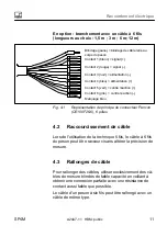
Page 49: ...c ble reli au corps du peson Fig 4 1 Repr sentation de principe du connecteur Pancon CE100F26 6 6 p les 4 2 Raccourcissement de c ble Lors de l utilisation de la technique 6 fils le c ble 6 fils du pe...

Page 50: ...ind s de faible capacit les c bles HBM satisfont ces condi tions S ne pas poser les c bles de mesure en parall le avec des lignes de puissance et des lignes de contr le Si ce n est pas possible prot g...

Page 51: ...e maximale 1 kg Port es maximales de 3 kg 200 kg Cn mV V 1 8 0 27 0 18 option 6 A1 1 8 mV V 0 1 2 0 0 2 option 6 A 2mV V 0 1 Z ro mV V 0 0 1 Coefficient de temp rature de la sensibilit 3 Plage temp 20...

Page 52: ...e de pr cision1 C3 MR Multi Range multi sensibilit s Nombre de graduations Unit 3000 Port e maximale Emax 2 kg 30 50 75 100 150 200 Valeur min d un chelon vmin g 2 5 5 10 10 20 Coefficient de temp rat...

Page 53: ...ement pour 100 VCC Ris GW 2 Plage nominale de la temp rature ambiante BT C 10 40 Plage d utilisation en temp rature Btu 10 50 Plage de temp rature de stockage Btl 25 70 Charge limite EL d Emax 150 Cha...

Page 54: ...2 1 8 0 18 2 0 0 2 2 4 0 24 Z ro 0 0 10 Coefficient de temp rature de la sensibilit 3 Plage de temp rature 20 40 C 10 20 C TKC de Cn 10 K 0 0087 0 0058 Erreur de r versibilit relative3 dhy de Cn 0 00...

Page 55: ...50 mm C ble et connect de raccordement informations voir page 31 12345678 week year v 19 1 M6x0 5 16 prof M6x1 6H 34 35 39 25 4 19 1 99 6 19 1 6 1 150 Direction de la charge SP4C3 MR 20kg SP4M 1 kg 18...

Page 56: ...www hbm com HBM Test and Measurement Tel 49 6151 803 0 Fax 49 6151 803 9100 info hbm com measure and predict with confidence A2447 1 1 7 2001 2447 HBM public...

Reviews: