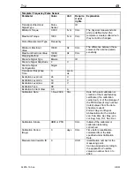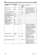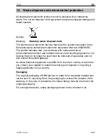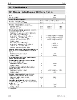
T12
42
A1979
−
10.0 en
HBM
Important
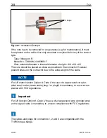
If plug 3 is used to power the device a tape wound core (toroidal core) is nec-
cessary to suppresse high frequencies in order to ensure compliance with
FCC regulations.
NOTE
Do not use cable KAB149 to connect the voltage output signal at AP01i to
ML01B of the MGCplus system!
This cable is only suitable for connecting the frequency output signal.
The analog output is designed as a monitoring output. The power
transmission of the torque transducer can cause interference on the
connected cable of up to 40 mV at 13.56 MHz. This interference can be
suppressed by connecting a 100 nF capacitor in parallel, directly at the
connected measuring instrument.
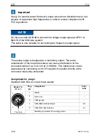
Assignment for plug 4:
Standard CAN Bus; A-coded, black washer
Top view
1
2
4
3
5
Binder 713
(M12x1)
Plug
pin
Assignment
Color
code
1
Shield
−
2
Not in use
−
3
CAN ground
−
4
CAN HIGH-dominant high
wh
5
CAN LOW-dominant low
bu
Shielding connected to housing ground
Summary of Contents for T12
Page 1: ...A1979 10 0 en Digital Torque Transducer T12 Mounting Instructions ...
Page 2: ......
Page 89: ...89 T12 A1979 10 0 en HBM ...
Page 90: ...T12 90 A1979 10 0 en HBM ...
Page 91: ......

