background image

20 


HBM T40MS 2020 en  (11.03.2020)                                HBM: public 

4.7  Speed measuring system, reference pulse 

The optional rotational speed measuring system (also with the additional reference 

signal and zero index option) is integrated into the transducer at the factory, 

so no installation is required. 


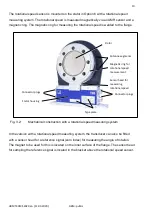
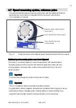
Fig. 4.7:  

Torque transducer with rotational speed measurement and reference signal 

 
Rotational speed measuring system sensor head alignment 
If the stator is accurately aligned for torque measurement, the rotational speed 
measuring system and the sensor for the reference signal (zero index) are also 
correctly aligned. So the two Allen screws on the sensor head (Fig. 5.10) must 

not be loosened. 

 
Important 

  You must not change the position of the sensor head. 

 
Important 

This is a magnetic rotational speed measuring system. 
In applications where magnetic strengths are expected to be high (such as an 
eddycurrent brake), suitable action must be taken to ensure that the max. 
magnetic field strength stated in the specification is not exceeded. 


Magnetic ring for rotational speed 
measurement 

Sensor head for the reference signal 


Sensor head for measuring 
rotational speed 

Summary of Contents for T40MS

Page 1: ...HBM T40MS 2020 en 11 03 2020 HBM public Mounting Instructions English T40MS...

Page 2: ...HBM T40MS 2020 en 11 03 2020 HBM public...

Page 3: ...2 Conditions on site 12 4 3 Mounting position 12 4 4 Installation options 12 4 4 1 Installation with subsequent stator mounting 13 4 5 Mounting the rotor 14 4 6 Mounting the stator 15 4 7 Speed measu...

Page 4: ...ntal protection 33 11Dimensions 34 11 1 Without speed measuring system 34 11 2 With speed measuring system 35 11 3 Adapter plate dimensions for easy center alignment of former T11 applications 36 12Or...

Page 5: ...sed with the installation of the product they must be used in order to ensure compliance with FCC regulations This device complies with Part 15 of the FCC Rules Operation is subject to the following t...

Page 6: ...2 HBM T40MS 2020 en 11 03 2020 HBM public Label example with FCC ID and IC number Label Fig 1 1 Location of the label on the stator of the device Fig 1 2 Example of the label...

Page 7: ...2 this device must accept any interference including interference that may cause undesired operation of the device Cet appareil est conforme aux norme RSS210 d Industrie Canada Cet appareil est confor...

Page 8: ...o the section Additional safety precautions Proper and safe operation requires proper transportation correct storage siting and mounting and careful operation Loading capacity limits The data in the t...

Page 9: ...considerations in such a way as to minimize residual dangers Pertinent national and local regulations must be complied with General dangers of failing to follow the safety instructions The T40MS torq...

Page 10: ...requirements Knowledge of the safety concepts of automation technology is a requirement and as project personnel you must be familiar with these concepts As automation plant operating personnel you h...

Page 11: ...This marking warns of a potentially dangerous situation in which failure to comply with safety requirements could result in death or serious physical injury CAUTION This marking warns of a potentiall...

Page 12: ...static and dynamic torques on stationary and rotating shafts Test beds can be extremely compact because of the short construction of the transducer This offers a very wide range of applications The T...

Page 13: ...on of excitation voltage and measurement signal are located on the measuring body s outer circumference The signals are sent and received by a separable antenna ring The antenna ring is mounted on a h...

Page 14: ...speed measuring system In the version with a rotational speed measuring system the transducer can also be fitted with a sensor head for a reference signal zero index for measuring the angle of rotatio...

Page 15: ...r the operating personnel of the system in which the transducer is installed Implement appropriate safety measures to avoid overloads and to protect against resulting dangers Use a screw locking devic...

Page 16: ...o static temperature ratios for example because of the temperature differences between the measuring body and the flange the values given in the specifications can be exceeded In this case ensure stat...

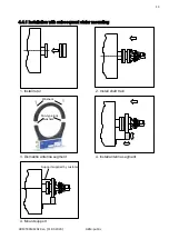
Page 17: ...0 HBM public 4 4 1 Installation with subsequent stator mounting 1 Install rotor 2 Install shaft train Washers Fan type lock washers 3 Dismantle antenna segment 4 Install antenna segment Support suppli...

Page 18: ...use DIN EN ISO 4762 hexagon socket screws of the property class stated in Table 4 1 in a suitable length dependent on the connection geometry see Table 4 1 on Page 14 We recommend DIN EN ISO 4762 fil...

Page 19: ...the stator has already been installed and is ready for operation The upper antenna segment can be separated from the stator for example for maintenance or to facilitate stator mounting If your applica...

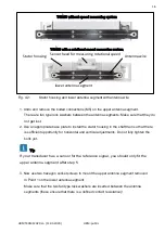
Page 20: ...housing in the shaft train so that there is sufficient opportunity for horizontal and vertical adjustments Do not fully tighten the bolts yet Tip If your transducer has a sensor for the reference sig...

Page 21: ...r in such a way that the antenna encloses the rotor more or less coaxially and the antenna wire in the axial direction shows the same position as the center of the transmitter winding on the rotor Fig...

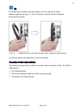
Page 22: ...shown in the photos Fig 4 4 Allignment of the rotor with the stator with a reference signal sensor 6 Now fully tighten the bolted stator housing connection Prevention of stator axial oscillation Depen...

Page 23: ...is a hole on the upper antenna segment with M5 internal thread which can be used to incorporate a clamping device see Fig 4 5 The cable plug also requires support in this case a construction example...

Page 24: ...surement the rotational speed measuring system and the sensor for the reference signal zero index are also correctly aligned So the two Allen screws on the sensor head Fig 5 10 must not be loosened Im...

Page 25: ...21 HBM T40MS 2020 en 11 03 2020 HBM public Fig 4 8 Torque transducer with sensor head for rotational speed measurement Never loosen the screws Sensor head for measuring rotational speed...

Page 26: ...portant The transducers are EMC tested in accordance with EC directives and identified by CE certification However you must connect the shiled of the connection cable on the shielding electronics encl...

Page 27: ...ransducer amplifier and indicator more than once Connect all devices in the measurement chain to the same grounded conductor In the case of interference due to potential differences compensating curre...

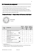
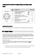
Page 28: ...gnment for plug 1 Supply voltage and frequency output signal Device plug Top view KAB153 KAB149 KAB178 1 Plug pin Assignment Color code D SUB plug pin HD SUB plug pin 1 Torque measurement signal frequ...

Page 29: ...speed measurement signal 2 pulse string 5 V 90 phase shifted gy 15 8 4 Reference signal 1 pulse revolution 5 V 2 bl 3 2 5 Not in use vi 6 Rotational speed measurement signal 2 pulse string 5 V 0 wh 1...

Page 30: ...en 11 03 2020 HBM public Fig 5 1 Ro tati on al sp ee d sig nal s at plug 2 rotational speed in the direction of the arrow Fig 5 2 Rotational speed signals at plug 2 rotational speed against the direc...

Page 31: ...nsducer is operated with a separated extra low voltage nominal rated supply voltage 18 30 VDC You can supply one or more T40MS torque flanges simultaneously within a test bench Should the device be op...

Page 32: ...wise it can be up to 20 m long If the permissible cable length is exceeded you can supply the voltage in parallel over two connection cables connectors 1 and 3 This enables you to double the permissib...

Page 33: ...al is electrically isolated from the supply voltage and the measurement voltage The transducer should not be under load when the shunt signal is being measured since the shunt signal is mixed additive...

Page 34: ...alignment Correct the rotor stator alignment Pulsating orange Rotor status cannot be defined Correct the rotor stator alignment If the LED still pulsates orange it is possible that there is a hardware...

Page 35: ...incorrect measured values in sequence are transmitted The measurement signals reflect the level of the defect status for the duration of the transmission defect approx another 3 3 ms Orange permanentl...

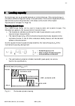
Page 36: ...libration performed for static measurements is also valid for dynamic torque measurements The natural frequency f0 of the mechanical measurement setup depends on the moments of inertia J1 and J2 of th...

Page 37: ...ccordance with national and local environmental protection and material recovery and recycling regulations old devices that can no longer be used must be disposed of separately and not with normal hou...

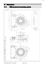
Page 38: ...34 HBM T40MS 2020 en 11 03 2020 HBM public 11 Dimensions 11 1 Without speed measuring system...

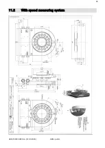
Page 39: ...35 HBM T40MS 2020 en 11 03 2020 HBM public 11 2 With speed measuring system...

Page 40: ...36 HBM T40MS 2020 en 11 03 2020 HBM public 11 3 Adapter plate dimensions for easy center alignment of former T11 applications...

Page 41: ...KAB153 6 Speed connection cable Binder 423 8 pin free ends 6 m 1 KAB154 6 Speed connection cable Binder 423 8 pin D Sub free ends 6 m 1 KAB163 6 TMC connection cable Binder 423 16 pin free ends 6 m 1...

Page 42: ...f signal span Frequency output 0 1 0 05 Voltage output 0 4 0 2 on the zero signal related to the nominal rated sensitivity Frequency output 0 1 0 05 Voltage output 0 2 0 1 Nominal rated sensitivity sp...

Page 43: ...pulse stability rpm 0 Pulse tolerance 7 degrees 0 05 Maximum permissible output frequency kHz 420 Group delay s 150 Radial nominal rated distance between sensor head and magnetic ring mechanical dist...

Page 44: ...s only apply for the nominal rated temperature range At temperatures 10 C load limits are expected to reduce by up to 30 because the strength reduction increases as the temperatures fall 13 With a sta...

Page 45: ...mm 0 02 0 02 0 001 Additional max radial deviation at lateral limit force mm 0 02 0 02 0 001 Additional plumb parallel deviation at limit bending moment at dB mm 0 06 0 06 0 006 Balance quality level...

Page 46: ...chooses the specified form and position tolerances surface quality and hardness for the connections provided Measuring range N m Axial run out tolerance mm Radial run out tolerance mm 500 2k 0 01 0 01...

Page 47: ...HBM T40MS 2020 en 11 03 2020 HBM public...

Page 48: ...anty and do not constitute any liability whatsoever nderungen vorbehalten Alle Angaben beschreiben unsere Produkte in allgemeiner Form Sie stellen keine Beschaffenheits oder Haltbarkeits garantie im S...

Reviews: