HBM T40MS 2020 en (11.03.2020) HBM: public
Specifications
(Continued)
12)
The influence of radial deviations, impact, defects of form, notches, marks, local residual magnetism, structural variations or material anomalies on the
vibrational measurements needs to be taken into account and isolated from the actual undulation.
13)
Above the nominal (rated) temperature range: ±1,5mm.
Notes:
•
Extremely high dynamic vibration, velocity, accelerations and running at shaft resonance
have to be avoided, otherwise measuring can be wrong or transducer can be damaged
(rotational acceleration max. 20.000rad/s
2
)!
•
Special torque transducers of type T40MS which will be used under „Formula 1“
conditions have a limited warranty of 250 working hours. Afterwards we recommend
replacing the sensor.
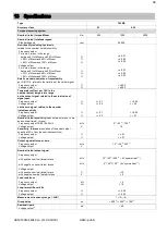
Nominal (rated) torque M
nom
N·m
500
1000
2000
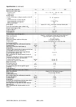
Mechanical values
Torsional stiffness c
T
kN·m/rad
550
550
1490
Torsion angle at M
nom
degrees
0,208
0,104
0,076
Stiffness in the axial direction c
a
kN/mm
900
900
3000
Stiffness in the radial direction c
T
kN/mm
460
460
1000
Stiffness during the bending moment round a radial
axis c
b
kN·m/deg.
7,7
7,7
19
Maximum deflection at longitudinal limit force
mm
<0,02
<0,02
0,001
Additional max. radial deviation at lateral limit force
mm
<0,02
<0,02
0,001
Additional plumb/parallel deviation at limit bending
moment (at Ød
B
)
mm
<0,06
<0,06
0,006
Balance quality level per DIN ISO 1940
G 2,5
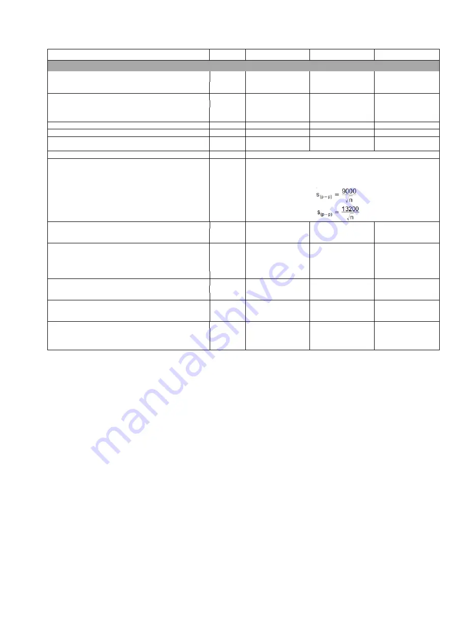
Max. limits for relative shaft vibration (peak-to-peak)
18)
Undulations in the connection flange area,
based on ISO 7919-3
Normal operation (continuous operation)
µm
(n in rpm)
Start and stop operation/resonance ranges (temporary)
µm
(n in rpm)
Mass moment of inertia of rotor J
v
without rotational speed measuring system
kg·m
2
0,0012
0,0012
0,0012
with magn. Rotational speed meas. System
kg·m
2
0,0016
0,0016
0,0016
Proportional mass moment of inertia for the
transmitter side (side of the flange with external
centering)
without magnetic rotational speed measuring system
% of J
v
51,2
51,2
51,2
with magnetic rotational speed measuring System
% of J
v
44,6
44,6
44,6
Max. permissible static eccentricity
of the rotor (radially) to the center point of the stator
±1
±1
±1
without rotational speed measuring system
mm
±1,5
±1,5
±1,5
Permissible axial displacement
between rotor an stator
19)
±1,5
±1,5
±1,5
Without rotational speed measuring system
mm
±1,5
±1,5
±1,5
Weight
Rotor without rotational speed measuring system
kg
approx. 0,8
approx. 0,8
approx. 0,8
Rotor with magn. Rotational speed meas. System
kg
approx. 0,95
approx. 0,95
approx. 0,95
Stator
kg
1,1
1,1
1,1
Summary of Contents for T40MS
Page 1: ...HBM T40MS 2020 en 11 03 2020 HBM public Mounting Instructions English T40MS...
Page 2: ...HBM T40MS 2020 en 11 03 2020 HBM public...
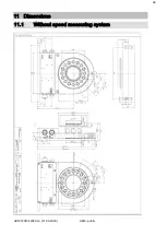
Page 38: ...34 HBM T40MS 2020 en 11 03 2020 HBM public 11 Dimensions 11 1 Without speed measuring system...
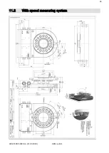
Page 39: ...35 HBM T40MS 2020 en 11 03 2020 HBM public 11 2 With speed measuring system...

