10
U3
HBM 11.12.2000
5
Mechanical installation
5.1
Important measures for installation
•
Treat the transducer gently.
•
Do not overload the transducer.
•
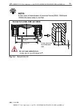
Either during installation or immediately afterwards, the transducer should
be bridged by a 50mm
2
stranded copper wire (highly flexible signal ground
cable EEK from the HBM line). The cable is attached by screws both above
and below the transducer. This prevents welding current flowing over the
transducer and welding the force introduction point.
WARNING
If there is a risk of breakage through overload on the transducer
and thus a risk to persons, additional safety measures are to be
taken.
5.2
General installation guidelines
The direction of measurement in which the forces work should be as much
towards the transducer as possible. Torsion and bending moments, eccentric
loading and transverse forces may result in measurement errors and if the
limit values are exceeded, could destroy the transducer.
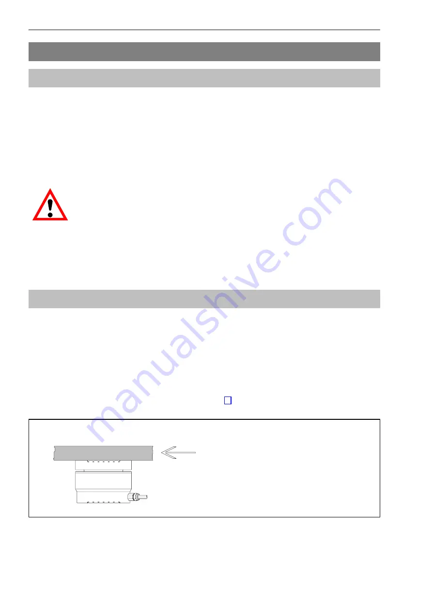
The transducer can take up 100% (80% at 50kN, 50% at 100kN) of its
nominal force as transverse force by reference to a force introduction point on
the force–introduction surface (see diagram Fig. 5.1), without losing its
mechanical competence.
Transverse force
Fig. 5.1
Transverse force introduction
SUNSTAR传感与控制 http://www.sensor-ic.com/ TEL:0755-83376549 FAX:0755-83376182 E-MAIL:szss20@163.com
SUNSTAR自动化 http://www.sensor-ic.com/ TEL: 0755-83376489 FAX:0755-83376182 E-MAIL:szss20@163.com


