15
VKK14 / VKK1
R
4
A23261.0 en/de/fr
H
BM
7
Special inst
r
uctions
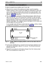
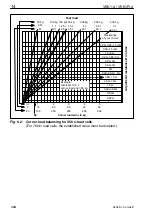
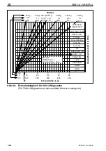
For other test loads types (e.g. building site
v
ehicle testing), the user can
extend the chart by dra
w
ing an additional line bet
w
een the zero point and the
actual test load used.
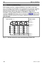
If the corner load errors are particularly high or if the load cells ha
v
e an input
resistance of more than 350
Ω
, it may be that the total
v
alue of the resistor
net
w
ork is insufficient. In these cases, remo
v
e the "0
Ω
resistor" (
R
19,
R
29,...,
R
69) and replace
w
ith a resistor of your choice. This resistance
w
ill be
added to that of the net
w
ork.
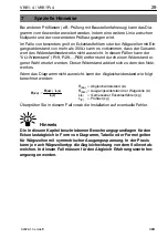
If the chart is not big enough, the adjustment resistance can be calculated as
follo
w
s:
R
(EA)
= adjustment resistance (
Ω)
R
(AW)
= output resistance of the load cell (
Ω)
L
(E)
= measured corner load error (kg)
L
(P)
= test load (kg)
R
(
EA
)
+
R
(
AW
)
·
L
(
E
)
L
(
P
)
In this case, you should first check the installation for possible errors.
Note
The bases fo
r
calculation desc
r
ibed in this section fo
r
co
r
ne
r
load
balancing and appea
r
ing in the fo
r
m of a cha
r
t, a table o
r
a fo
r
mula,
apply to load cells with a symmet
r
ical output voltage. In p
r
actice, the
balancing effect may diffe
r
f
r
om the ta
r
get value, depending of the type
of load cell involved. In this case, you will have to use empi
r
ical values
fo
r
balancing.


