13
VKK14 / VKK1
R
4
A23261.0 en/de/fr
H
BM
6
Technical
r
ecommendations
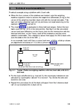
Practical example using a platform
w
ith 4 load cells:
D
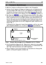
When the four corners of the platform are loaded, note the
w
eighing
machine signals in order to assess the respecti
v
e differences (in kg) to the
corner of the
w
eighing machine (load cell)
w
ith the lo
w
est indication. This
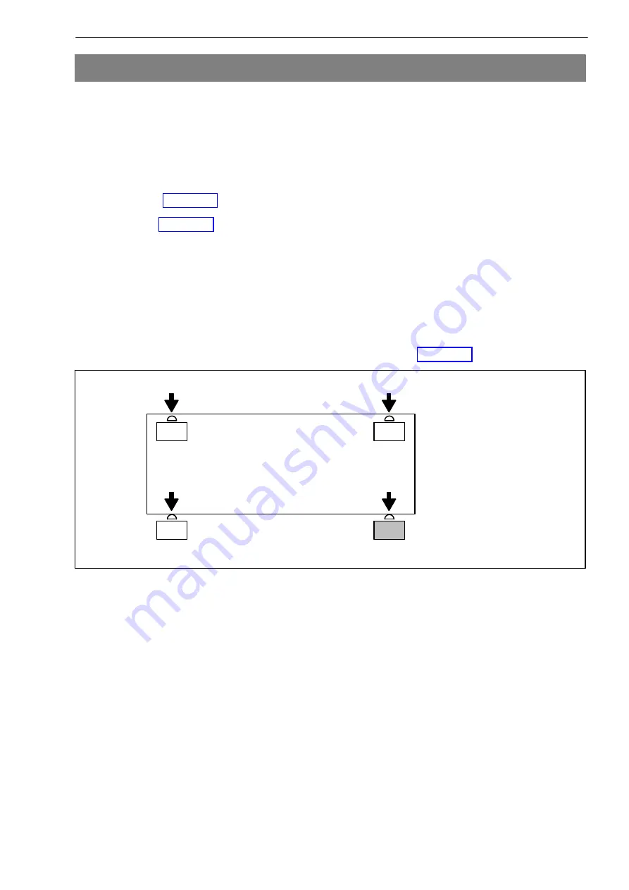
load cell is the reference load cell (4) and does not need balancing (in the
example in Fig.6.1, load cell 4).
D
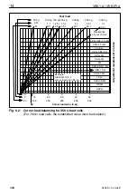
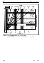
The chart (Fig.6.2) is graduated in three test load ranges. Select the test
loads used (50kg...30t) in the rele
v
ant line. Starting from the calculated
corner load error difference on the Xaxis, look for the intersection
w
ith the
test load and then, on the Yaxis, read off the resistance and the most
suitable combination. The resistance
v
alues here apply for 350
Ω
load cells
(see the table in the lid of the VKK...).
In our example, load cell 3 has a corner load error of 80kg,
w
hich produces
an adjustment resistance of 1.5+0.82
Ω
(sho
w
n in Fig.6.2).
Load cell 1
12,600 kg
Load cell 2
12,550 kg
Load cell 3
12,530 kg
R
efe
r
ence load cell 4
12,450 kg
Test load
12.5 t
(Example:
R
eference load cell +80kg)
Fig.6.1:
Typical Platfo
r
m weighing machine with fou
r
load cells with 12.5t
test load
D
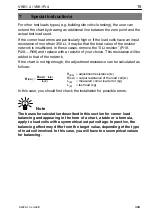
For the load cell affected (e.g. load cell 3), the necessary resistances are
acti
v
ated by opening the rele
v
ant "0
Ω
resistor". Tip: Di
v
ide the
w
ire and
bend it to one side
D
R
epeat this procedure for all the load cells apart from the ’reference load
cell’ (in our example, this is load cell 4).


